Get in touch with Zejiang Paper Machinery Company


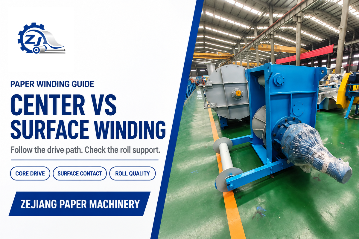
The difference between center winding vs surface winding is where the drive applies torque. A center winder rotates the core through a shaft or chuck; a surface winder rotates the growing roll through contact with a driven roller, drum or belt. Center-surface winding combines the two drive paths.
Contact alone does not identify the method. A center winder can have an undriven lay-on roller, while a surface-supported design can handle sensitive webs when its contact loading is controlled. To compare the two arrangements for a paper mill or converter, examine how each handles the required web tension, roll weight and surface pressure during the roll build.
Winder selection quick reference
- A lay-on roller doesn’t automatically make a center winder surface-driven.
- Center drive enters at the core; surface drive enters through outer contact.
- Specify web tension in N or N/m, roll diameter in m, roll mass in kg and line speed in m/min.
- Compare the full roll build, transfer and unloading cycle.
Center Winding vs Surface Winding at a Glance
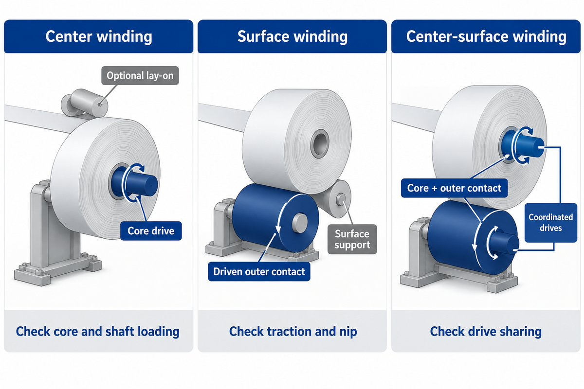
Select center winding when the core drive provides the required tension control and the core-support configuration can carry the finished roll. Consider surface winding when distributed support and controlled contact suit the material. Center-surface winding is available when surface support is necessary, with a separate adjustable contribution from core torque.
| Decision point | Center winding | Surface winding | Center-surface winding |
|---|---|---|---|
| Drive entry | Core, through shaft or chucks | Outer roll through driven contact | Core and outer contact |
| What sets roll rotation | Core-drive speed and torque | Peripheral speed at the driven contact | Coordinated core and surface drives |
| Roll-weight path | Often through core support; added support is possible | Drum, belt or another designed support arrangement | Shared according to machine geometry |
| Contact with outer layers | Optional lay-on or other contact | Required for drive transmission | Required while surface drive contributes |
| Nip adjustment | Available when a lay-on is fitted | Part of traction and roll formation | Coordinated with the core-torque contribution |
| Growing-diameter demand | Core drive spans changing torque and rpm | Contact geometry and load change as the roll grows | Drive sharing and load schedules change |
| First mechanical limit to examine | Core grip, shaft loading and torque-speed range | Traction, nip loading and supported-roll geometry | Those limits plus control coordination |
| Useful reason to shortlist | Direct core torque with optional light contact | Roll support through the outer surface | Extra control over how torque enters the roll |
| Acceptance evidence | Stable build from core to full diameter | Stable build without damaging contact or slip | Stable build through changes in drive sharing |
This classification applies across web winding, including paper, plastic film, textile, nonwovens and laminate. It describes the winding mechanism rather than the whole converting line. The production-stage distinction is separate: see Pope reel and slitter rewinder roles when deciding whether the project needs parent-reel formation or downstream finishing.
| Useful advantage | Corresponding limitation |
|---|---|
| Center drive offers direct core-torque control with optional lay-on contact. | The core, shaft and drive must cover the full roll load and torque-speed envelope. |
| Surface drive can support the roll through its outer surface. | Traction and contact loading must remain compatible with the web. |
| Center-surface drive adds a controlled core-torque contribution. | Drive sharing needs coordination with the contact and loading system. |
How a Center Winder and a Surface Winder Support the Roll
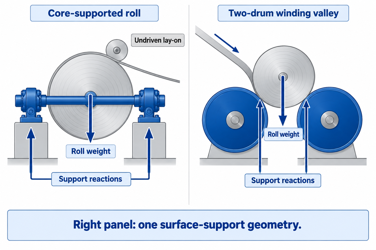
A center winder drives the core, but its shaft, chucks and any support rollers determine how the weight is carried. A surface winder drives through outer contact; a two-drum cradle is just one option, not the universal surface winder. In the winding process, the support drawing is just as important as the drive label.
The winding shaft or mandrel must grip the core and transmit torque without unwanted movement. As the winding roll increases in size, the loads on its supports change. A larger motor does not increase the bending capacity of an existing shaft or the strength of a paper core.
The different paper-machine roll types guide divides the functions of the process and support rolls in the mill.
“A lay on roller adds nip load to a center winder.”
An undriven lay-on follows the roll surface while the core supplies the drive. Calling that arrangement surface winding would hide the actual power path. A turret winder describes how winding stations change position, so turret layout and drive architecture should be specified separately in slitter rewinder configurations.
What is a winding valley?
A winding valley is the cradle between two support drums in which the growing roll sits. The drums support the roll across its width and driven drum contact rotates it. Roll weight, drum spacing and any rider-roll loading influence the contact forces as diameter increases.
This geometry is typical of two-drum winding.
Weight support can help with a heavy roll, but the resulting nip loads must suit the web. A horizontal surface configuration, belt support, or center assistance modifies that load path. Stating all surface winders are the same valley machine can thus lead to the wrong conclusion about paper sensitive to nips.
Web Tension, Nip and Torque: What Each Control Changes
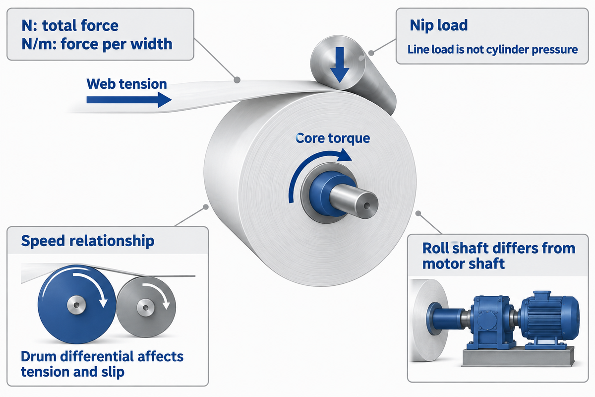
Web tension pulls along the moving web; nip load presses against the building roll; drive torque supplies rotation. They affect roll formation together. A center-surface layout introduces ways of adjusting their contributions, yet friction and contact geometry still tie the response of one control to the others.
TAPPI’s winding education treats tension, nip and torque as related control subjects. “Torque control” needs particular care in a quotation: a core drive always transmits torque, even when the operator interface expresses its command as tension.
| Control variable | What changes | Useful distinction |
|---|---|---|
| Incoming web tension | Longitudinal force before the web enters the roll | Total force in N differs from force per width in N/m |
| Nip load | Contact force against the roll | Line load differs from cylinder pressure and local contact pressure |
| Core torque | Drive contribution through the core | Motor torque and roll-shaft torque differ when gearing or losses intervene |
| Speed relationship | How the driven members move relative to the web | Drum-speed differential changes local tension and slip |
In winding, the incoming tension is also different from the tension added to the outer lap and the stresses retained deeper in the wound layers. Yanabe and Nagasawa’s surface-winding simulation shows why geometry, interlayer friction and drum speeds affect the stress distribution. A controller screen with similar settings doesn’t make two mechanical arrangements equivalent.
Then air removal introduces a second compromise. Contact can help exclude entrained air at high speeds, while excessive pressure can compress or mark the web. Reducing the nip until marking disappears may leave a different roll-quality problem.
The actuator, loading and actual web path all influence adjustment possibilities.
A tension-control loop also requires an identified measuring and controlling region. Paper-machine control loops provide the wider control context. In gap winding, the separated roll receives no surface-drive torque across the air gap; core drive must supply the required rotation.
Roll Diameter: The Torque and Speed Trade-Off
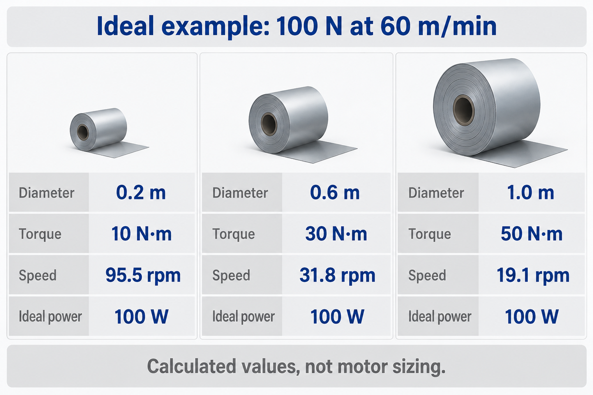
For an assumed total web force of 100 N at 60 m/min, increasing roll diameter from 0.2 m to 1.0 m raises ideal shaft tension torque from 10 N·m to 50 N·m. Shaft speed falls from 95.5 rpm to 19.1 rpm. The same web force still moves at the same linear speed.
Think of pulling a strap around a growing wheel: the force acts through a longer lever arm, but each revolution also takes up more web. The rotational work and power relationships in the 2016 OpenStax textbook University Physics give the following calculation, with no slip, gearing, acceleration, losses or tension taper included.
- Roll-shaft tension torque: T = F × D ÷ 2, with F in N and D in m.
- Roll speed: n = v ÷ (π × D), with v in m/min and n in rpm.
- Ideal web power: P = F × v ÷ 60 watts when v is in m/min.
| Roll diameter | Tension torque | Roll speed | Ideal web power |
|---|---|---|---|
| 0.2 m | 10 N·m | 95.5 rpm | 100 W |
| 0.6 m | 30 N·m | 31.8 rpm | 100 W |
| 1.0 m | 50 N·m | 19.1 rpm | 100 W |
At the middle diameter, the calculation is 100 × 0.6 ÷ 2 = 30 N·m, and 60 ÷ (π × 0.6) = 31.8 rpm. Multiplying torque by angular speed gives approximately 100 W. That agreement is a handy unit check.
Suppose the buyer wants to increase the finished-roll diameter without changing the line speed. At the small diameter near the start, the shaft needs the higher rotational speed; near the end, it needs the higher tension torque. The indicated torque-speed envelope must encompass both points.
During acceleration, the drive must also change the motion of the rotating mass. This illustration isolates the contribution from the steady winding so that the supplier can add the actual mechanical loads to it; 100 W isn’t a motor recommendation.
Kim and colleagues’ roll-to-roll study likewise separates the no-slip speed relation from the fuller dynamics involving inertia and friction. Lower shaft torque by itself isn’t evidence of lower electrical energy consumption.
Which Winding Method Fits Tissue, Coated Paper and Kraft?
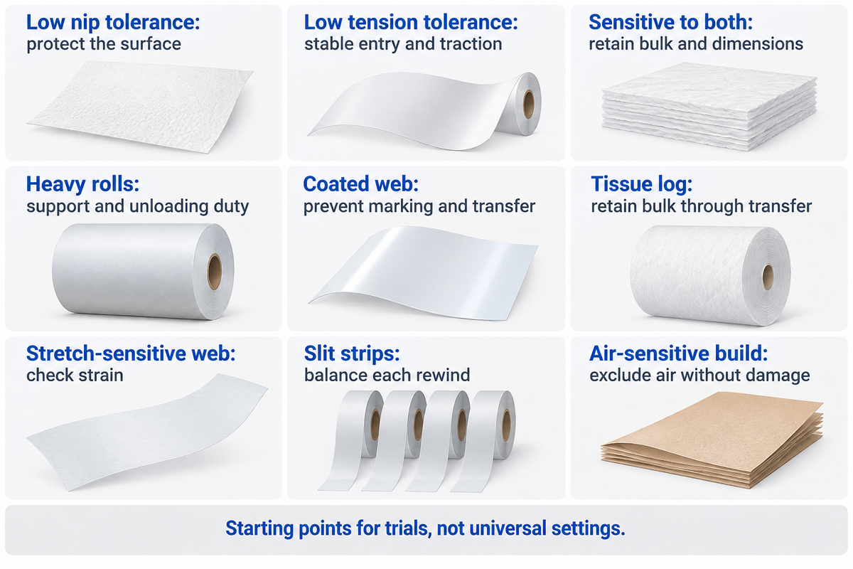
For tissue, look at surface drive arrangements with controlled low-pressure contact to retain bulk and support the log; for coated paper, compare core drive with controlled lay-on contact; for heavy kraft rolls, compare drum-supported surface or center-surface arrangements with sufficient unloading capacity. Grade names narrow the trial requirements, but nip sensitivity and tensile response can vary within each grade.
The two-axis nip–tension selection matrix separates sensitivity to compression from sensitivity to pulling force. It’s a starting point for comparing machinery. Speed, friction, contact path and roll support remain additional constraints. The TAPPI Journal research on winding and contact pressure explains how surface damage can arise from more than one pressure source.
| Web or operating condition | Starting arrangement to compare | What must work in the trial |
|---|---|---|
| Low nip tolerance; moderate tension tolerance | Center drive with carefully controlled lay-on contact | Surface remains acceptable while air is excluded |
| Low tension tolerance; adequate nip tolerance | Surface drive or center-surface with low incoming tension | Stable web entry and sufficient traction |
| Sensitive to both nip and tension | Low-load supported arrangement with coordinated controls | Bulk and dimensions survive the full roll build |
| Heavy roll; strong web; adequate contact tolerance | Drum-supported surface or center-surface design | Support, nip growth and unloading remain within duty |
| Coating prone to marking or blocking | Controlled contact surface and load, with suitable core drive | No print-through, sticking or coating transfer |
| Compressible tissue log | Tissue-specific low-pressure surface support or other proven log-building design | Required bulk with a stable log through transfer |
| Elastic or stretch-sensitive web | Stable low-tension zone with suitable support | Acceptable machine-direction strain after unwinding |
| Slit strips with differing build diameters | Appropriate individual or differential rewind control | Each strip builds without unacceptable tension imbalance |
| Air-sensitive build at higher speed | Adjustable lay-on/contact path compatible with the drive | Air exclusion without surface damage or instability |
Let’s say a tissue converter is considering equipment for a soft, bulky grade. The purchasing shortlist says “center winding” because the material is delicate. However, production requires stable support while the log grows and shifts between positions.
Surface-driven tissue designs can provide that support with controlled low-pressure contact. Therefore, the test needs to examine bulk retention along with log stability, rather than exclude every machine with a driven contact roll. Quality should judge the finished product, while production observes the transfer and acceleration portions of the cycle.
The relevant goal is a repeatable log that survives converting.
Keep that finished-log application separate from parent-web production in the tissue paper machine process. Historical tissue-winding patent disclosures also describe center and surface combinations; no single drive name belongs exclusively to tissue.
Roll Quality: Find the Limit Before Changing the Winder
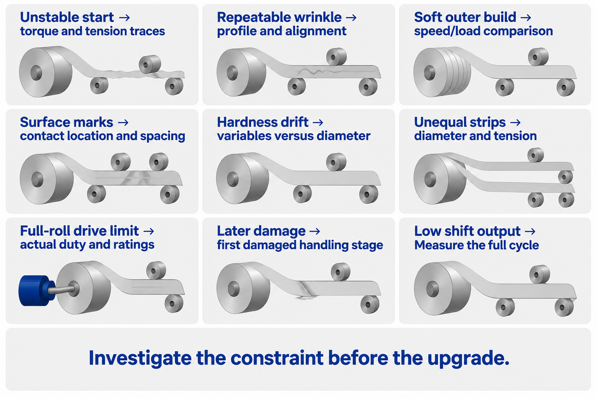
A wrinkle, soft start or telescoped roll doesn’t reveal the source of its defect by its visual appearance alone. Separate incoming-web problems, control problems during the rewinding process and damage after winding. The common-sense indication is whether the defect “travels” with the material, a specific roll-build stage, a contact position or a subsequent handling event.
David Roisum’s winding-myth analysis distinguishes defects associated with high tension, low tension and causes that don’t respond to tension. Reducing tension across every recipe can trade one problem for another. The following roll-build bottlenecks connect observations to measurements.
| Observation | Possible constraint | Next measurement or comparison |
|---|---|---|
| Unstable start near the core | Core grip, start sequence or early loading | Compare torque and tension traces during the first build stage |
| Wrinkle at a repeatable transverse position | Alignment or incoming web profile | Compare the incoming profile and roller alignment |
| Soft or air-filled outer build | Air exclusion or contact-loading schedule | Compare builds at different validated speed/load combinations |
| Surface marking at contact | Local pressure, covering or contamination | Match mark spacing and location to the contacting member |
| Changing hardness across diameter | Actual tension/nip profile differs from the recipe | Record the controlled variables against measured diameter |
| Strip-to-strip differences after slitting | Caliper variation or rewind control distribution | Compare slit-strip diameter and tension behavior |
| Drive limit near full roll | Torque-speed envelope or mechanical loading | Compare actual duty with drive and support ratings |
| Good roll at discharge; damage later | Clamp, storage or transport pressure | Document the first stage at which damage appears |
| Rated speed achieved; low shift output | Changes, core loading or unloading | Time the complete cycle, including stopped periods |
A tapered tension command needs its shape recorded against diameter, not just a final percentage. For specialty materials, adhesion, elastic modulus and the tendency to compress affect how that recipe behaves. Preserve the same web, core and handling conditions when comparing winding results; otherwise the machine change and material change become inseparable.
Cost Comparison: Pay for Control You Will Use
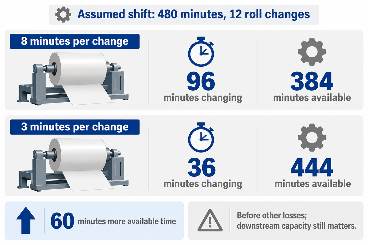
Drive coordination, shaft requirements and handling requirements affect package price, so compare quotations at the same finished-roll duty and automation scope. Center surface equipment has coordinated drives, but surface support can change the shaft and unloading scheme.
The value of those differences follows the constraint they remove: poor quality, a drive limit, slow roll changes or difficult unloading. Roisum’s review of web-handling myths explains why extra nip traction capacity can add equipment and maintenance costs when slipping is not the problem.
The difference is 60 minutes of available running time. Example: assume a 480-minute shift with 12 roll changes. At 8 minutes each, changes consume 96 minutes, leaving 384 minutes before other losses. At 3 minutes each, they consume 36 minutes, leaving 444 minutes.
For a plant manager comparing those two options, the saved hour may move the queue instead of becoming saleable output if the next process is already full. Finance can value the hour using the contribution per productive hour on the site, less the added cost of maintenance and operation before comparing the higher purchase cost. Procurement must keep assumptions the same between quotes: same number of changes, operator involvement, roll sizes and acceptance quality.
This calculation helps distinguish useful automation from a higher headline speed.
“Fully automatic” requires a specified boundary. Core loading, securing the tail end, and roll discharge are separate tasks.
In-line slitters or equipment that can perforate the web add process functions beyond the basic winding mechanism. Commissioning, supported controls and service access belong in the cost comparison alongside mechanical capacity.
Integration and Utility Requirements for a Paper Rewinder
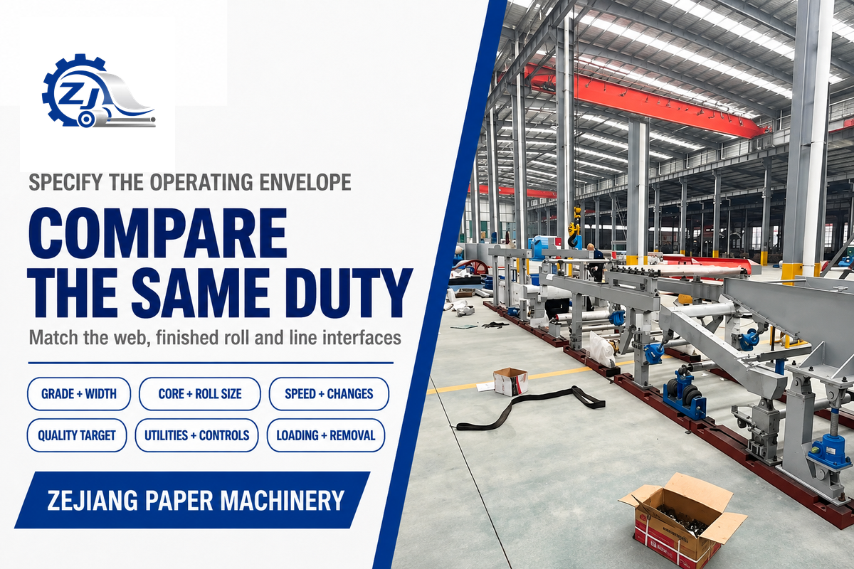
Indicate the incoming web, finished-roll envelope and interfaces prior to comparing a paper rewinder quotation. The vendor requires sufficient information to match the core support, drive range and handling scheme to the line. Utility demand then follows the selected equipment and operating cycle, rather than a generic center-versus-surface label.
Zejiang builds and rebuilds paper machinery and mill components, with machining, balancing and inspection facilities described in our manufacturing capabilities. A rebuild review should include the existing shaft/core arrangement and control interfaces as well as the desired new duty.
For a comparable proposal, send:
- Paper grade, basis weight, width and surface sensitivity.
- Core dimensions; minimum and maximum finished-roll diameter and mass.
- Required line speed, acceleration cycle and roll-change frequency.
- Roll-quality targets, downstream unwind conditions and representative samples.
- Existing drive/control details, electrical supply, compressed-air availability and layout.
- Core loading, finished-roll removal and the acceptance-test scope.
For a new installation or a rebuild, review paper rewinder and Pope reel equipment with the intended input and output rolls in view. Send your roll dimensions and winding requirements so the proposal can address the actual limit in your line.
Frequently Asked Questions
Is center-surface winding the same as center winding?
No. Center-surface winding combines core drive with driven contact at the roll surface.
Center winding applies drive torque through the core, even when an undriven lay-on roller touches the roll. The combined arrangement offers an additional way to distribute the drive contribution, but its usable control range still follows the mechanical layout, traction and web properties. Incoming web tension, nip load and core torque remain related variables because the contacting surfaces transmit force through friction.
Can a center winder use a lay-on roller?
Yes. A center winder can use a lay-on roller to apply nip loading while the core remains driven.
The roller may help control air entering the roll and affect roll formation. Its presence doesn’t change the drive classification unless it also supplies surface-drive torque. The loading system and contact path determine how much nip adjustment is available throughout the build.
Is surface winding always better for large rolls?
No. Surface support can make a large or heavy roll practical, but nip sensitivity, friction and contact geometry remain part of the choice.
Center winding can also handle substantial rolls when its core, shaft, bearings and drive are sized for them. Compare the complete support and unloading arrangement at the required full-roll duty. Roll mass, shaft bending and core strength can set different limits from the drive motor itself.
Is a turret winder a separate winding method?
No. A turret describes the roll-change arrangement.
Center, surface or combined drive principles may be used within a machine’s station design, so turret layout and winding method are separate specifications.
What information should I give a paper rewinder supplier?
Give the supplier a complete operating envelope, beginning with the actual paper and the rolls you need to produce.
Include grade, basis weight, web width, core dimensions, finished diameter and roll mass. State both the normal operating speed and the expected acceleration and changeover cycle. A sample of a good finished roll helps explain the quality target more clearly than a request for “high-performance” machinery. For an existing line, add its layout, drive and control interfaces, utility supply and handling method. Explain when any current defect first appears and whether it changes with diameter, speed or material. Include the next process’s unwind requirements. These details let the proposal connect the winding arrangement to usable output, installation work and acceptance criteria instead of relying on a machine name.
References & Sources
- Neal Michal: Winding Part 3, Tension, Nip and Torque – PFFC, 2023.
- David R. Roisum: web handling and winding myths TAPPI conference paper, 2007.
- Web handling and converting courses TAPPI course catalogue.
- University Physics, Volume 1, section 10.8 Moebs, Ling and Sanny, OpenStax, 2016.
- Experimental web handling in a two-actuator roll-to-roll system Kim et al., Sensors, 2022.
- Pressures on webs in wound rolls due to winding and contact Mollamahmutoglu, Ganapathi and Good, TAPPI Journal, 2014.
- Simulation of winding web on surface winder Yanabe and Nagasawa, JSME, 2020.
- US8210462B2: Winding apparatus and method technical disclosure, Kimberly-Clark Worldwide.