Get in touch with Zejiang Paper Machinery Company


Updated October 2026. Reviewed by the Henan Zejiang Paper Machinery Co., Ltd. technical team.
Hydraulic symbols are the standard shapes and lines that show what each part of a fluid power circuit does and how the parts connect. ISO 1219-1:2012 defines the symbols, and ISO 1219-2:2012 sets the rules for drawing the circuit. This document covers the basics of schematic drawings the way a maintenance technician would, then shows how to apply the method to press, calender and reel stand circuits on a paper machine.
Hydraulic symbols are standardized drawings of parts of fluid power circuits. Circles represent pumps and motors, squares represent valves, diamonds represent filters and coolers, and different line styles represent working, pilot and drain lines. Each symbol shows function and connections only. Size, port position, flow rate and pressure are shown on the nameplate and data sheet.
Key points
- The words “open center” name two different port patterns. Read the ports in the neutral box. Don’t read the name.
- Function and connections are shown with flow paths. Size, port position, flow rate and pressure are given on nameplates and data sheets.
- Connections are shown with blocked ports in a neutral box. They don’t promise that a cylinder holds position.
- Read a circuit in four passes: energy, control, actuator and return. Verify loading force with F = p × A.
- Relieve stored energy before opening a line. The energy is stored in the accumulator after the pump stops.
Quick reference
- Symbols: ISO 1219-1:2012, with Amd 1:2016
- Circuit diagram rules: ISO 1219-2:2012
- Valve mounting surfaces: ISO 4401:2005
- Catalogue status checked on 28 October 2026
Hydraulic Symbols: Four Shapes and Four Line Types in Circuit Diagrams
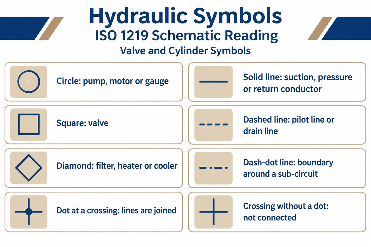
Hydraulic symbols use four basic shapes: the circle, square, diamond and arrow. They also use four line types: solid, dashed, dash-dot and hose arc. Circles are drawn for pumps, motors and gauges, squares for valves, and diamonds for filters and coolers. Each symbol shows the function of the hydraulic component, not its size.
Fluid power specialist Josh Cosford puts it at 99 percent of symbols building on a circle, square or diamond, as he explains in Hydraulic symbology 101. The solid line is the basic line: it outlines every shape and also draws the lines that represent suction, pressure and return conductors. The dash-dot line encloses a group of parts that work as one unit, such as a pilot-operated directional valve or a safety sub-circuit, and the enclosure is generally a four-sided polygon, in practice a rectangle.
A dashed line is used to draw pilot lines and drain lines. Pilot lines signal other valves, and drain lines give leakage fluid a path. A pilot line terminates at a valve control port, and a drain line terminates at a tank.
The joining of hydraulic lines is clear in machine drawing. Whether it be hose, tube, or pipe, lines must show whether they join or just cross. If they join, a dot is placed at the joint. If they cross, with no dot, they are considered to be separate. This is described in Machine Design. Hoses are arcs with dots at both ends. In older drawings, a crossing was shown as a jump or a bridge, and currently, lines are simply crossed.
One term to keep apart: a hydraulic headbox is a stock-flow design, not a fluid power circuit. The term hydraulic headbox in Zejiang’s headbox guide names the type that relies on fan-pump pressure and a designed distribution channel.
What are the four basic shapes used in hydraulic schematics?
The four basic shapes are the circle, the square, the diamond and the arrow or triangle. Circles are pumps, motors and gauges; squares are valves; diamonds are conditioning devices such as filters, heaters and coolers; and the triangle shows the direction of flow of the fluid. The table gives the basic symbols and line types and describes them.
| Symbol type | What it means |
|---|---|
| Circle | Pump, motor or gauge; also used for check valves |
| Square | Valve; one square for each position of a directional valve |
| Diamond | Filter, heater or cooler |
| Solid triangle | Direction of fluid flow; outward on a pump, inward on a motor |
| Diagonal arrow | The part is adjustable |
| Solid line | Working line: suction, pressure or return conductor |
| Dashed line | Pilot line or drain line |
| Dash-dot line | Boundary around a compound component or sub-circuit |
| Arc with a dot at each end | Flexible hose |
| Dot at a crossing | The lines are joined |
| Crossing without a dot | The lines are not connected |
| Cup | Reservoir, also called the tank |
ISO 1219 vs ANSI and CETOP: Which Fluid Power Standard Drew the Schematic
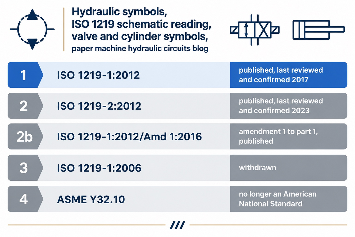
ISO 1219-1:2012 is the current symbol standard for fluid power schematics, and ISO 1219-2:2012 is its companion for circuit diagrams. The 2006 edition of part 1 is withdrawn, and ASME lists the older ANSI Y32.10 as no longer an American National Standard. The table below gives the status of each document, and ISO reviews a standard every 5 years.
The older ANSI set looks much the same. According to a 2006 trade textbook chapter from Hydraulics & Pneumatics, ANSI changed its symbols in 1966 to remove written information, and so the two sets have similar layouts, and either may be used in the United States. Many companies use the ISO symbols with foreign suppliers and customers.
Symbols provide a shared language, so engineers and technicians in different countries read the same drawing, and the set covers components in hydraulic systems and pneumatic ones. Plants also modify the standard symbols to suit local habit, which the same chapter says confuses novices. Accurate interpretation starts with the legend on the drawing, then the supplier’s catalog. For new drawings, use ISO 1219-1:2012, and keep older ANSI-based drawings readable with their own legends. For a drawing marked CETOP, the European Oil Hydraulic and Pneumatic Committee that ISO lists as a liaison organization in nine of its committees, including ISO/TC 131 for fluid power systems, ask the equipment maker which symbol set it follows.
| Standard | Covers | Status |
|---|---|---|
| ISO 1219-1:2012 | Graphical symbols for conventional use and data-processing applications | Published; last reviewed and confirmed 2017 |
| ISO 1219-1:2012/Amd 1:2016 | Amendment 1 to part 1 | Published |
| ISO 1219-2:2012 | Circuit diagrams | Published; last reviewed and confirmed 2023 |
| ISO 1219-1:2006 | Earlier edition of part 1 | Withdrawn |
| ASME Y32.10 | Graphic symbols for fluid power diagrams | No longer an American National Standard; kept for historical reference |
Are hydraulic and pneumatic symbols the same?
Hydraulic and pneumatic symbols are based on the same standard and have the same shape, thus, aren’t separate alphabets. According to the same chapter on Hydraulics & Pneumatics, symbols cover both hydraulic and pneumatic components, with any exceptions noted. Check the legend of the drawing for the medium before interpreting symbols.
Hydraulic Pump, Motor and Cylinder Symbols
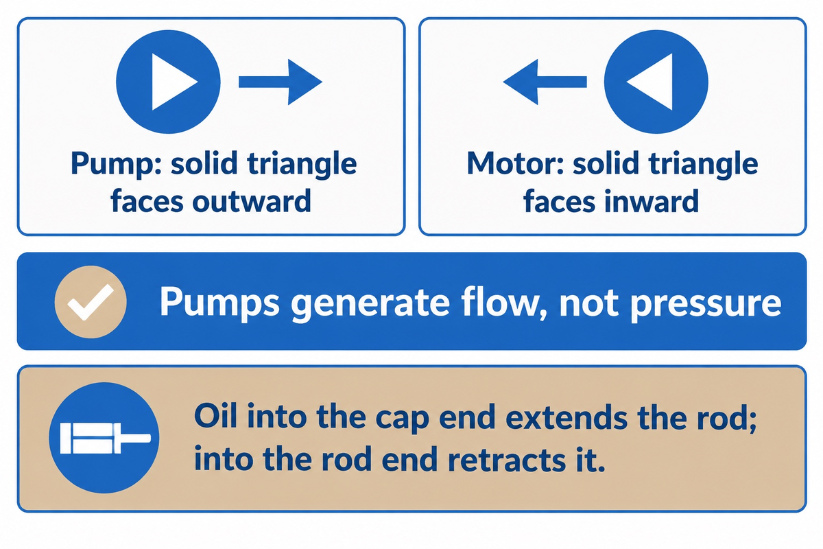
Pumps and motors are both circles, and the triangle tells them apart: on a pump the solid triangle faces outward, on a motor it faces inward. The technical college text calls this the basic difference between pump and motor symbols.
Pumps generate flow, not pressure. The fixed-displacement pump lesson brings the symbol along with its coupling, electric motor, reservoir and filter. Variable displacement pumps are often drawn with an arrow inside the circle, and a diagonal arrow on any symbol indicates that the part is adjustable.
Hydraulic motors are often bi-rotational, so their symbol carries a triangle at both ports, and some pumps can also run as motors. Motors turn hydraulic pressure into rotational force, converting pressure into rotary motion.
Cylinders convert hydraulic pressure into linear motion, so a double-acting cylinder produces movement and force in both directions. It works like a piston and rod in a barrel, where oil entering the cap end extends the rod and oil entering the rod end retracts it. Single-acting cylinders rely on gravity or a spring to move in one direction, as the double-acting cylinder lesson explains.
Directional Control Valve Symbols: Open, Closed and Tandem Center
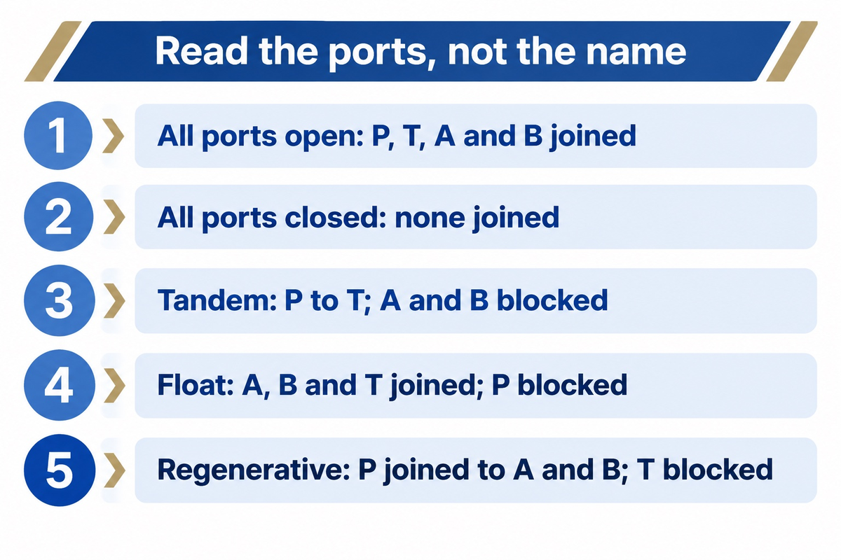
Directional valves steer fluid flow and pressure to one side of an actuator or the other. Four working ports and three positions define a 4/3 directional valve, and its neutral box shows which of ports P, T, A and B are connected or blocked when the valve is centered.
P is the pressure inlet, T returns to the tank, and A and B feed the actuator, as the 4/3 valve lesson shows. Each square represents one position, so a valve is drawn as three connected squares, and springs return the spool to the middle one.
Neutral-Box Rule: Read the Ports, Not the Name
The Neutral-Box Rule: describe a valve’s centered position by which of P, T, A and B are connected or blocked, never by its name.
There is a rule because the names are used loosely. The 2007 Power & Motion textbook chapter defines open center as all four ports open. Some practitioners in engineering forums use the same terms for P to T with A and B blocked, which that chapter and an NPTEL lecture call tandem center. The terms also name whole circuits. The chapter pairs open-center valves with fixed-volume pumps and closed-center valves with pressure-compensated pumps.
| Center type | Ports connected | What the box does | Source |
|---|---|---|---|
| All ports open | P, T, A and B joined | Pump flow returns to tank at little backpressure; the cylinder floats under outside forces | Power & Motion |
| All ports closed | None joined | Blocks pump flow; spool bypass still leaks into A and B | Power & Motion |
| Tandem | P to T; A and B blocked | Pump unloads to tank while the actuator ports are blocked | NPTEL, Power & Motion |
| Float | A, B and T joined; P blocked | Work ports move freely; pump flow passes the relief valve | NPTEL, Power & Motion |
| Regenerative | P joined to A and B; T blocked | Adds speed in one direction | NPTEL |
Blocked ports in a box show connections, not a guaranteed hold. A metal-to-metal spool valve will cause fluid to leak out into A and B, and will pressurize both ends of a single-rod cylinder, approximately at half the system pressure. The differential area between the cap end and the rod end will then push the cylinder out, slowly. As mentioned in the same chapter, a lock on a cylinder in a multi-actuator circuit can be accomplished using either a float-center valve and pilot-operated check valves, or a counterbalance valve on a vertically oriented cylinder.
Tandem valves also cost pressure. A hollow spool adds backpressure, and some listings show a lower nominal flow. The backpressure of tandem valves in series is also additive. This chapter states that a circuit with three tandem-center valves in series can require more than 300 psi to unload the pump, losing energy and lowering system performance.
Choosing a center for a roll-loading cylinder starts with the hold. An open center works best with a circuit that has one valve and one actuator, since the free path to the tank starves any other valve on the pump. Tandem center unloads the pump but adds backpressure. Closed center serves several actuators from a pressure-compensated pump, but the spool bypass won’t hold a single-rod cylinder. If the cylinder needs to hold position in a multi-actuator circuit, use the float center route with pilot-operated check valves, or use a counterbalance valve.
Does a 4/3 spool valve work in an in-between position?
Standard 4/3 valves work in one of their drawn positions, and between them the spool is only in transit. Spool lands overlap the ports, so flow starts after a slight delay as the spool shifts. Valves built to hold in-between positions are a different type, the infinitely variable or proportional valves.
Pressure Reducing, Relief and Sequence Valve Symbols
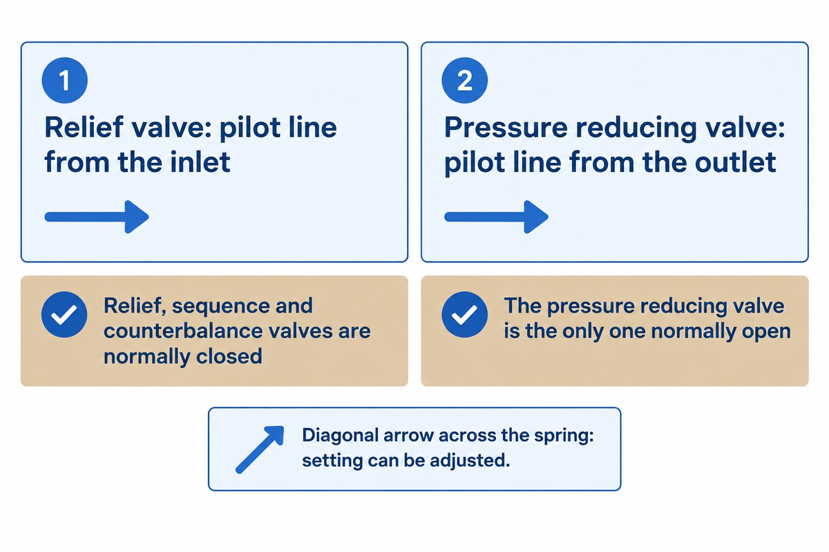
Every pressure control valve is drawn as a single square, and the arrow indicates whether it passes or blocks flow at rest. Relief, sequence and counterbalance valves are normally closed; the pressure reducing valve is the only one that’s normally open. Diagonal arrows across the spring mean the setting can be adjusted.
Relief valves relieve pressure by diverting fluid to the reservoir when pressure rises above the set pressure, protecting pumps and actuators, as explained in the relief valve lesson. Its dashed pilot line senses the inlet pressure. The valve opens on the pressure difference between the signal and the spring setting. In a pressure reducing valve, the pilot line senses the downstream pressure. Therefore, a pressure reducing valve closes when downstream pressure increases above the spring setting. In Cosford’s example, rising pressure acts through the pilot line, and as it keeps increasing the pilot force starts to overcome the spring force, so the valve opens and holds upstream pressure at that setting.
In Fluid Power World’s pressure valve article, a sequence valve is a relief valve with a drain line and a lower pressure setting. Counterbalance valves open when they sense pilot pressure from the rod port and the reverse flow check valve allows the cylinder to extend with a low pressure drop. Sequence valves with an integrated check valve are drawn with a small check valve in parallel with the main path.
Reading a reducing valve as a relief valve inverts the circuit. Following the pilot line solves it. A pilot line from the inlet means a relief valve. A pilot line from the outlet means a pressure reducing valve.
Flow Control Valve Symbol and Check Valve Symbols
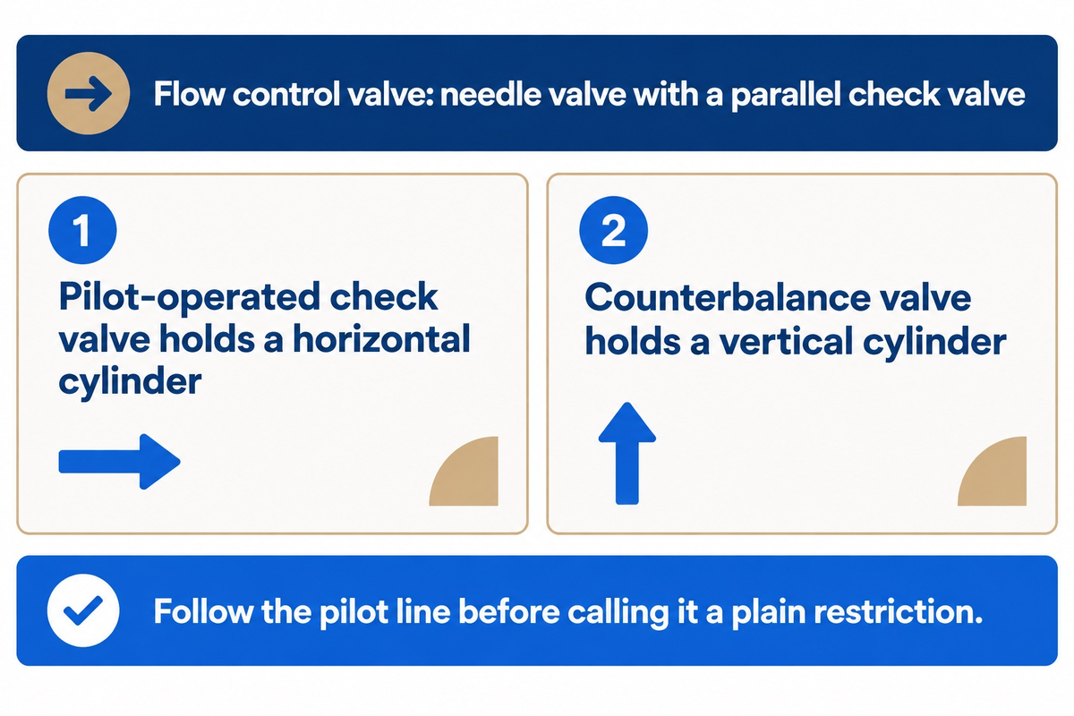
Flow control valves are drawn as a needle valve in line with a check valve in parallel. The adjustable orifice sets the flow rate in one direction, and the parallel check valve passes fluid almost unrestricted in the other direction. Ghost lines around both show a single valve body, as the flow control valve lesson describes.
Check valves on their own are one-way elements, and circles are used for them as well as for pumps and gauges. Machine Design suggests writing the spring pressure next to a check valve symbol, because the symbol doesn’t show it.
When a check valve is pilot-operated, a dashed pilot line connects it to the pressure that opens it, so follow that line before calling the valve a plain restriction. In a cylinder line, a pilot-operated check valve holds a horizontal cylinder against external forces, and a counterbalance valve holds a vertical one.
Hydraulic Fluid, Filter, Tank and Accumulator Symbols
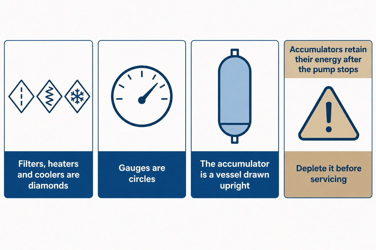
Filters, heaters and coolers are drawn as diamonds, and gauges are circles. These are the supporting symbols around the valves covered above. The accumulator is a vessel drawn in an upright position. The solid triangle is a hydraulic fluid direction marker. The drawing rules for hydraulic schematics keep a reservoir and an accumulator upright, even if other symbols are rotated.
Filters are diamonds with a dashed line, which trap particles as fluid passes. Coolers show 2 outward arrows to show heat leaving the fluid. The tank symbol can be repeated across the schematic without meaning several tanks, so each return shows where it ends without extra connections.
What does the solid triangle symbol represent in hydraulic schematics?
The solid triangle shows the direction of fluid flow from a pump through a circuit. Drawn on its own, it represents a power unit. When drawn on a pump, it faces outward and on a motor, it faces inward.
An accumulator has a gas side and a liquid side, and most circuits use it to store energy, a 2014 Power & Motion article explains. A 2014 Power & Motion article explains that the ideal gas precharge is typically 80% of the minimum working pressure. The same article rates welded diaphragm accumulators to typically no more than 5000 psi and threaded ones to some 10,000 psi.
⚠️ Important
Accumulators retain their energy after the pump stops. The University of Minnesota safety office warns that accumulators store energy that stays hazardous with the machine off, and Power & Motion says to deplete it before servicing, typically through accumulator safety valves or ball valves.
Paper Machine Hydraulic System: Press, Calender and Reel Stand Circuits
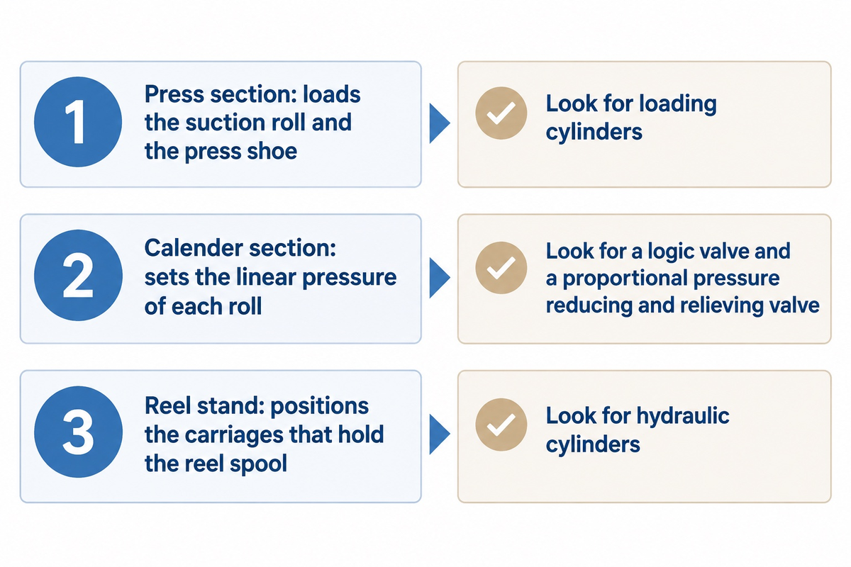
On a paper machine, hydraulic circuits load, and support and position rolls. The same symbols from the sections above apply to these circuits. They press rolls together in the press and calender sections, support the shells of deflection-compensated rolls, and move the carriages of the reel stand. The valve-level detail of each section is on the machine’s own schematic.
An equipment feature hosted by TAPPI describes a first press nip with a hydraulically loaded suction roll, and a shoe-press roll whose press shoe is loaded hydraulically through force and loading cylinders on a rigid, non-rotating shaft. The same feature says the calender section controls the linear pressure of each roll and monitors load cells. Yang and Xu’s 2012 paper on a soft roll calender describes a hydraulic system built around a logic valve and a solenoid proportional pressure reducing and relieving valve.
A US patent describes hydraulic cylinders at the reel stand that position the carriages holding the reel spool to set the nip load at the reel-up. Roll support is a separate circuit: deflection-compensated rolls usually have a stationary axle and a hydrostatically supported rotating shell, and a 2023 peer-reviewed paper lists the high energy use of that hydrostatic system as its main drawback. Researchers have tested aerostatic bearings for the same application as a concept.
| Location | What the circuit does | Symbols to look for |
|---|---|---|
| Press section | Loads the suction roll and the press shoe; supports deflection-compensated shells | Loading cylinders |
| Calender section | Sets the linear pressure of each roll | Logic valve; proportional pressure reducing and relieving valve |
| Reel stand | Positions the carriages that hold the reel spool | Hydraulic cylinders |
Four scope items in a loading package
The roll or reel, the loading cylinders, the power unit and the control valves are separate scope items in a loading package. Zejiang’s press, vacuum and couch rolls guide, calender rolls guide and pope reel guide give roll and reel scope. List the cylinders, the power unit and the valves as separate items in the enquiry, and name who issues the schematic.
How to Read Hydraulic Schematics in Four Passes: A Press Loading Circuit
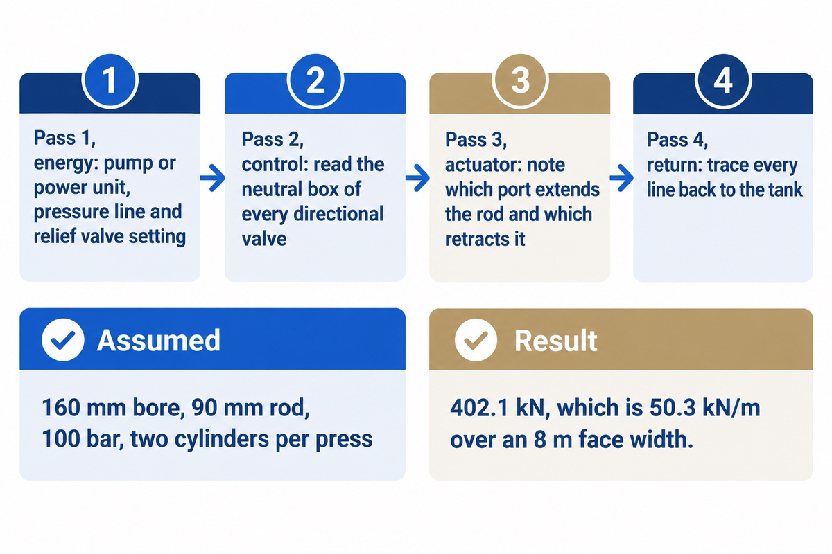
Read a hydraulic schematic in four passes: energy, control, actuator and return. One pass at a time keeps a long drawing from turning into a tangle of lines, and the order works for any circuit, including a press loading circuit.
4-Pass Schematic Read: Energy, Control, Actuator, Return
The 4-Pass Schematic Read traces a circuit in four passes: energy source, control valves, actuator, and return to the tank.
- Find the energy: start at the pump or power unit, follow the solid triangle out along the pressure line, and note the relief valve and its setting.
- Trace the control: follow each valve square, the control elements of the circuit, read the neutral box of every directional valve, and follow the dashed pilot lines to the valves they operate.
- Locate the actuator: find the cylinder, and note which port extends the rod and which retracts it.
- Follow the return: trace every line back to the tank, passing the filter and cooler diamonds.
Tracing the flow on the schematic is how a hydraulic consultant starts a pressure problem, in the Machinery Lubrication article on low system pressure. The force check comes after the trace. Assumed inputs: a double-acting cylinder with a 160 mm bore and a 90 mm rod, a system pressure of 100 bar, two cylinders per press and a roll face width of 8 m, with losses ignored.
| Quantity | Value | How it is found |
|---|---|---|
| Bore | 160 mm | Assumed input |
| Rod diameter | 90 mm | Assumed input |
| System pressure | 100 bar (10 MPa) | Assumed input |
| Cylinders per press | 2 | Assumed input |
| Roll face width | 8 m | Assumed input |
| Piston-side area | 201.1 cm² | π/4 × (0.16 m)² |
| Force per cylinder, rod extending | 201.1 kN | 10 MPa × 0.020106 m² |
| Total loading force | 402.1 kN | 2 × 201.1 kN |
| Line load | 50.3 kN/m | 402.1 kN ÷ 8 m |
| Force per cylinder, rod retracting | 137.4 kN | 10 MPa × π/4 × (0.16² − 0.09²) m² |
On these inputs the two cylinders push 402.1 kN, which is 50.3 kN/m over an 8 m face width. That compares loading setups. It is not a nip load, because real nip load also depends on the loading arm geometry and roll weight. For a bore diameter of 2.0 inches at 1000 psi, the same formula gives 3,142 pounds of extension force, as LibreTexts works it.
For scale, Krochak and Östlund’s 2017 pilot-scale press trials at RISE in Stockholm ran shoe-press linear loads of 100, 500 and 1000 kN/m with a nip about 260 mm long, and roll-nip loads of 50, 150 and 250 kN/m with a nip about 25 mm long. The 2014 review says conventional wet presses may apply as much as 200 kN/m and that industrial shoe presses reach up to 1500 kN/m. TAPPI Journal states load pressure in kN/m or pounds per linear inch.
How do you read hydraulic schematic symbols?
Read hydraulic schematic symbols by shape first, line second, and marks last. Shape names part family. Line denotes connection. Arrows and triangles add direction and adjustability. Use the legend if the drawing has one, then trace the circuit with the four passes above. The roll is then specified from its drawing and the press roll page lists the inputs Zejiang requests, including the paper grade and the operating nip load.
Hydraulic Circuit Troubleshooting from the Schematic
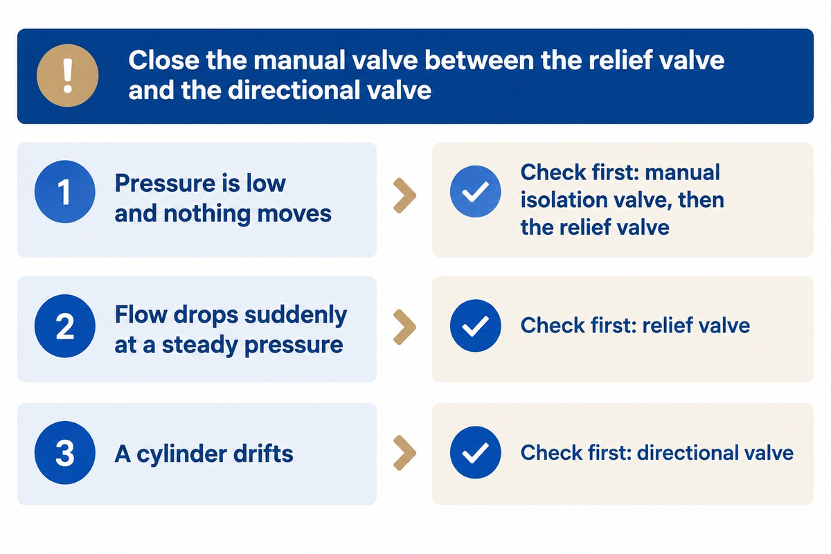
With an accurate schematic, isolate the power supply by closing the manual valve between the relief valve and the directional valve. That check works from the same schematic that the four passes above taught you to read. If pressure then builds and the relief valve dumps, the power supply works and the fault is downstream. Otherwise the fault is in the power supply.
These should be treated as first checks, taken from a hydraulic consultant’s article and one practitioner rule.
“In my experience, once a pressure problem is encountered, the first component to be changed is the hydraulic pump. This frequently is a mistake.”
Jack Weeks, GPM Hydraulic Consulting, Machinery Lubrication, April 2020
| Symptom | Symbol to check first | What the reading tells you |
|---|---|---|
| Pressure is low and nothing moves | Manual isolation valve, then the relief valve | Pressure builds when the valve is closed: look downstream. No change: check the suction strainer, then the relief valve. A relief valve that will not adjust may be stuck open |
| Flow drops suddenly at a steady pressure | Relief valve | A sudden drop at one pressure points to a relief valve opening; a steady fall from low to high pressure points to a leak path or a worn pump |
| A cylinder drifts | Directional valve | Cap lines A and B, put hand-pump pressure on P with a gauge, run T to a bucket: pressure should hold for at least one minute. A tandem-center valve can only be tested in its A and B positions |
To test the pump itself, the consultant installs a flow meter in the relief valve tank line, turns the relief setting down so pump flow dumps at low pressure, then raises it. If the pump holds flow at normal system pressure it is good, and if flow falls as pressure rises it should be replaced. For starting checks of a new line, see the paper machine commissioning guide.
⚠️ Important
Relieve stored energy before opening any line. In the USA, 29 CFR 1910.147 requires that potentially hazardous stored or residual energy be relieved, disconnected, restrained and otherwise rendered safe, and requires verification that isolation is complete before work starts. Depressurize the entire system including accumulators.
Replacement Valve or Cylinder RFQ: What to Copy from the Drawing
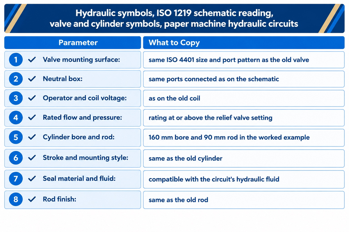
Copy the nameplate and parts-list fields into a replacement valve or cylinder request, because a symbol shows function, flow paths and connections only, not size, port location, flow rate or pressure. The drawing says what the part does, and the nameplate says how big it is. ISO 4401:2005 sets the mounting surfaces of four-port directional valves so that valves fit, and a matching surface does not make two valves equivalent.
The roll pages from Zejiang consistently show the same habit for rolls. The press roll page calls for the roll drawing, paper grade, and operating nip load, and the calender roll page asks for the existing roll drawing or measurements, the material class, hardness target, and a fit of the journal and bearings.
Copy these fields into the quote request:
| Parameter | Recommended range | Why it matters | How to verify |
|---|---|---|---|
| Valve mounting surface | Same ISO 4401 size and port pattern as the old valve | The standard fixes mounting dimensions for fit, nothing about performance | Compare the old valve’s nameplate with the new data sheet |
| Neutral box | Same ports connected as on the schematic, for example tandem: A and B blocked, P to T | A different center changes what a loaded cylinder does | Compare the box on the schematic with the data sheet symbol |
| Operator and coil voltage | As on the operator symbol and the old coil | The symbol shows a solenoid, not its voltage | Nameplate and parts list |
| Rated flow and pressure | Pressure rating at or above the relief valve setting (the worked example runs at 100 bar system pressure); flow rating at or above the pump flow | The schematic prints no flow or pressure | Data sheet curves at your working pressure |
| Cylinder bore and rod | 160 mm bore and 90 mm rod in the worked example | Bore and rod diameter set the force in both directions | Drawing, or measure the old cylinder |
| Stroke and mounting style | Same as the old cylinder | The symbol shows no dimensions | Parts list; measure the old cylinder |
| Seal material and fluid | Compatible with the circuit’s hydraulic fluid | Symbols do not show construction | Parts list and supplier data sheet |
| Rod finish | Same as the old rod | The symbol does not show the surface | Parts list; inspect the old rod |
Tandem-center valves usually list a lower nominal flow or higher pressure drop in supplier catalogs, therefore, ask for the flow rating at your working pressure. For a rebuild instead of a replacement, the paper machine rebuild guide addresses the scope questions.
Hydraulic Symbols FAQ
Q: Have hydraulic symbols changed?
Yes. ISO 1219-1:2012 replaced the 2006 edition, and ANSI Y32.10 is no longer an American National Standard.
Smaller changes also took place. Crossing lines used to be drawn with a jump or bridge, while the current convention simply crosses them and marks a joint with a dot. If a drawing looks bizarre, find out which convention it follows before reading the symbols.
Q: What does the continuous line symbol represent in hydraulic schematics?
Continuous lines are working lines: suction, pressure or return lines.
The same line outlines every shape. Machine Design shows pressure and return lines as single lines, and pilot lines as dashed or dotted. Follow a line from the pump along the pressure side and back to the tank on the return side.
Q: Where can I get a hydraulic symbols PDF or CAD library?
The standard itself is the reliable source: ISO sells ISO 1219-1:2012 as a PDF, listed at CHF 227 on 28 October 2026.
Use the ISO 1219-1:2012 symbols from the standard itself or from a CAD library that names that edition. Valve and cylinder makers print the symbol for their own parts in their catalogs, and the Hydraulics & Pneumatics chapter advises looking there first when a part has no standard symbol.
Q: How do I tell a hydraulic pump from a hydraulic motor on a schematic?
Look at the triangle in the circle: it faces outwards on a pump and inwards on a motor.
Both are circles, so the direction of the triangle is the best way to differentiate them. Bi-rotational motors also have a triangle at both ports, and some pumps are also motors.
Q: What does a diagonal arrow through a hydraulic symbol mean?
Diagonal arrows signal that a part is adjustable.
In a relief valve, it is across the spring and means the pressure setting can be changed. In a pump, an arrow in the circle is one way to show variable displacement.
Q: What is the symbol for a hydraulic accumulator?
An accumulator is shown as a vessel, and according to the drawing rules, it is shown in an upright position.
It represents a vessel with a gas side and a liquid side. Most circuits store energy in it. Regard that energy as live until it has been released.
Q: Is a hydraulic headbox the same as a hydraulic circuit?
No. In a headbox, hydraulic names a type, not a fluid power circuit.
In Zejiang’s headbox guide, the hydraulic type relies on fan-pump pressure and a designed distribution channel for higher-speed, tightly controlled delivery, with a typical band of 500–1,800 m/min quoted on that page. It moves paper stock, so the symbols in this guide don’t apply to it.
Planning a press, calender or reel stand enquiry?
Send the drawing of the roll/reel, the paper grade, and the operating nip load, and keep the hydraulic schematic with them.
How this guide was prepared. It draws on ISO and ASME catalogue pages checked on 28 October 2026, technical-college and university teaching texts, trade-press articles and the United States stored-energy rule. Zejiang manufactures paper machines, mill components and rebuilt equipment, and this guide does not describe a Zejiang hydraulic system.
References & Sources
- ISO 1219-1:2012, graphical symbols, ISO
- ISO 1219-2:2012, circuit diagrams, ISO
- ISO 4401:2005, valve mounting surfaces, ISO
- CETOP liaison record, ISO
- ASME Y32.10, fluid power symbols, ASME
- 29 CFR 1910.147, control of hazardous energy, OSHA
- Hydraulic Safety, University of Minnesota
- Hubbe (2014), paper strength review, BioResources 9(1)
- Krochak and Östlund (2017), press nip geometry, RISE, hosted by BioResources
- Aerostatic bearing for large rotor (2023), Aalto University
- Hydraulic Systems, module 5, lecture 5, NPTEL
- Rules for drawing hydraulic schematics, LibreTexts
- Hydraulic symbology 101, Josh Cosford
- Hydraulic circuit symbols, Machine Design
- Hydraulic symbology 203, pressure valves, Fluid Power World
- Chapter 4, ISO symbols, Hydraulics & Pneumatics
- Chapter 10, directional control valves, part 3, Power & Motion
- Accumulators add functionality to hydraulic circuits, Power & Motion
- 4 steps to diagnose low system pressure, Machinery Lubrication
- Paper machine equipment feature, May 2003, TAPPI
- TAPPI Journal, July 1997, TAPPI
- Hydraulic system for a soft roll calender (2012), Applied Mechanics and Materials
- US Patent 6,913,223 B2, Google Patents
- Operation of a hydraulic motor, LibreTexts
- Fixed-displacement pumps, LibreTexts
- Double-acting hydraulic cylinder, LibreTexts
- 4/3 directional control valve, LibreTexts
- Cylinder force output when extending, LibreTexts
- Relief valve function, LibreTexts
- Flow control valve and its symbol, LibreTexts