
Get in touch with Zejiang Paper Machinery Company


Quick Specs: What to Record Before Diagnosis
- Process duty: coarse, fine, fractionation, broke, or approach-flow screening
- Feed: furnish, grade, flow in m³/h, and consistency in percent
- Hydraulics: inlet pressure, accept pressure, differential pressure, and valve positions
- Mass balance: accept flow, reject flow, reject consistency, and fiber loss
- Mechanical condition: motor load in kW, vibration in mm/s, bearing temperature in °C, and noise
- Quality: contaminant count, freeness or fractionation response, and downstream runnability
A pressure screen is a closed pulp-screening vessel used in a pulp and paper mill to separate usable fiber and remove larger contaminants from pulp while stock moves under controlled pressure. Stable operation depends on the screen, furnish, feed system, reject loop, instruments, and downstream demand working as one system. This guide shows operators how to read those relationships before changing a valve, cleaning a basket, or blaming the machine.
Updated July 2026. Written for paper mill engineers, stock-preparation managers, maintenance teams, and equipment buyers. Technical scope reviewed against published academic, industry, and regulatory sources.
Bottom line
A Pressure Screen is stable only when flow, consistency, pressure, reject, power, vibration, and accept quality agree. Trend the full signal set against the same-duty baseline, then verify the process and physical condition before changing a setpoint.
TL;DR
- Counterintuitive: a lower differential pressure can signal lower feed, an instrument problem, bypassing, or enlarged apertures rather than a healthier screen.
- Capacity starts with a dry-solids and hydraulic balance; no public evidence supports one universal capacity coefficient.
- Rotor speed, reject, and pressure changes must stay inside the commissioned window for the actual furnish and basket.
- Open the vessel only under the OEM procedure, site isolation rules, and applicable hazardous-energy controls.
- Repeated plugging or quality drift may originate in the pulper, cleaner, pump, dilution, reject loop, or downstream process.
What a Pressure Screen Does in Stock Preparation
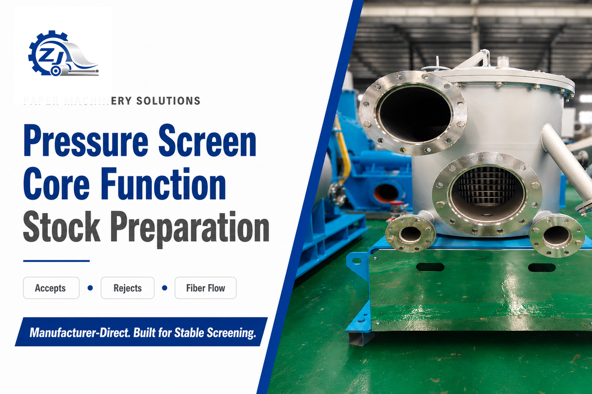
A pulp-and-paper pressure screen continuously divides pumped stock into feed, accept, and reject streams. Fibers, also written as fibre in many mill documents, move to the accept side when they can pass the basket holes or slots; retained contaminants and some usable fiber leave through the reject outlet. For paper manufacturers, success is not the lowest possible reject. It is high-quality accepted stock, high fiber recovery, and stable operation across the intended paper grades.
Long fiber content also changes the required balance.
A North Carolina State University thesis reviews the vessel, screen cylinder, rotor, and linked flow paths as one separation system. Basket openings provide the geometric barrier, while the rotor’s pressure pulses limit mat buildup near the aperture. Its literature synthesis treats feed consistency, reject rate, pressure difference, slot velocity, and temperature as linked factors that can affect removal and yield.
In recycle and virgin-fiber papermaking lines, pressure screens are used at different points in stock-preparation and pulping equipment systems. Coarse screens may face a larger contaminant burden; fine screens protect later process stages; a machine-screen duty may prioritize a uniform sheet and runnability. For example, a fine-screen duty can retain normal pressure while contaminant carryover rises, so the accept sample and physical basket condition still need verification. Installed duty determines what “good” accept and reject streams mean.
Key takeaway: Judge the screen by the required separation duty and mass balance, not by one pressure reading or a low-reject target.
How Pressure, Rotor Pulses, and the Screen Basket Separate Stock
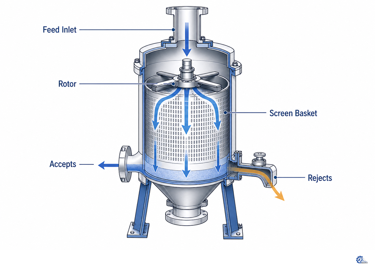
Separation occurs because stock meets a perforated or slotted basket while a rotor repeatedly changes the local pressure near its surface. Desirable fibers pass through holes or slots when geometry and hydraulic loading allow; larger or less flexible impurities remain on the feed side and travel toward the reject path. Tangential entry and centrifugal effects may redistribute stock inside the vessel, but the installed flow path and basket geometry determine the actual response.
- Feed the vessel. The pump delivers pulp suspension to the inlet at the flow and operating consistency required for the duty.
- Distribute the stock. Tangential or axial flow, cylinder geometry, and inlet design influence how stock reaches the basket.
- Pass the aperture. Fibers pass through a drilled hole or slot when their geometry, flexibility, and orientation permit.
- Clear the surface. A passing foil or rotor element produces positive and negative pressure behavior that disrupts the fiber mat and helps keep apertures clear.
- Discharge both streams. Accepted stock leaves through the outlet; rejected stock carries retained material toward treatment, recovery, or disposal.
Research in a Canadian experimental thesis links foil geometry, pulse frequency, screen-cylinder geometry, slot velocity, inlet design, capacity, and power. A complementary North Carolina State literature review treats consistency, reject rate, pressure difference, slot velocity, and temperature as linked screening variables. Together, those sources explain why rotor design and clearance matter without supplying a transferable tip speed or gap for every machine.
Inflow and outflow describe the direction stock crosses the basket. Common catalog labels for types of pressure screens include inflow pressure screen, outflow pressure screen, and, in some markets, shield screen. Because terminology varies, verify any “rotating screen basket” label against the drawing and confirm whether stock travels inward or outward through the basket. Slotted baskets may emphasize separation by particle shape and flexibility, while drilled baskets use holes. Name the flow configuration and aperture when diagnosing wear, but keep model and type selection on the commercial page.
Key takeaway: The basket creates the separation boundary; the rotor preserves usable open area. Geometry, flow, furnish, and condition decide how well that pair works.
Build the 9-Signal Screen Health Loop
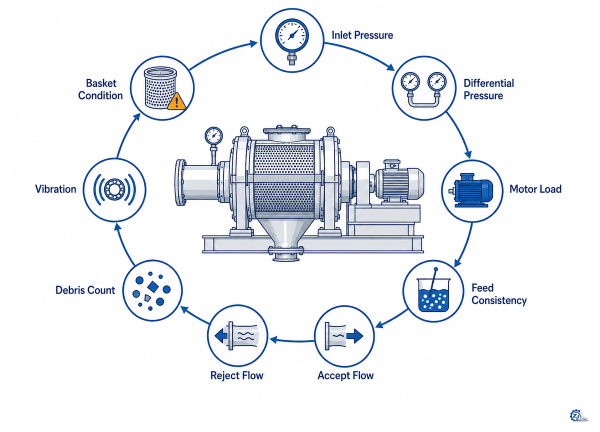
This 9-Signal Screen Health Loop correlates nine readings at matched grade, furnish, production rate, and screen duty. The linked-variable treatment in the North Carolina State pressure-screen review supports reading consistency, reject rate, pressure difference, slot velocity, and temperature together. This is a screening tool, not a universal fault finder. Treat a changed signal as meaningful only when another process reading and physical or quality verification confirms it.
| Signal | Direction to notice | Possible interpretation | Corroborating check | First safe action |
|---|---|---|---|---|
| 1. Feed flow | Up, down, or cycling | Production change, pump instability, valve movement, or restriction | Pump speed, chest level, valve position | Restore the approved same-duty condition |
| 2. Feed consistency | Higher, lower, or variable | Changed hydraulic loading and mat formation | Sampler, dilution flow, furnish change | Verify measurement before dilution changes |
| 3. Inlet pressure | Rising or unstable | Feed restriction, loading change, or pump-control issue | Feed flow and upstream pressure | Check the feed system and instrument |
| 4. Accept pressure / DP | Rising, falling, or cycling | Blinding, low flow, bypass, wear, or downstream restriction | Both pressure transmitters and accept flow | Validate instruments before a setpoint move |
| 5. Accept flow | Loss or unexpected gain | Reduced open area, feed change, or enlarged opening | Dry-solids balance and accept quality | Reconcile flow with consistency |
| 6. Reject flow / mass reject | Higher, lower, or thickening | Valve, dilution, contaminant-load, or recovery change | Reject consistency and fiber content | Protect the reject path from blockage |
| 7. Motor load / power | Rising, falling, or oscillating | Hydraulic load, rubbing, deposits, or lower feed | Flow, pressure, vibration, and sound | Stop escalation if contact is suspected |
| 8. Vibration / temperature | New pattern or upward trend | Imbalance, bearing, deposit, seal, or contact concern | Route, speed, lubrication, and baseline | Apply the site’s mechanical escalation rule |
| 9. Accept quality / fiber loss | Contaminant drift or yield loss | Wear, fractionation shift, reject change, or upstream upset | Lab result, reject sample, downstream response | Confirm quality before equipment action |
| Measurement category | Commissioned reference | Sample at 0 min | Sample at 30 min |
|---|---|---|---|
| Feed flow | 250 m³/h | 247 m³/h | 243 m³/h |
| Feed consistency | 2.0% | 2.0% | 2.1% |
| Inlet pressure | 320 kPa (3.20 bar) | 318 kPa (3.18 bar) | 326 kPa (3.26 bar) |
| Differential pressure | 45 kPa (0.45 bar) | 46 kPa (0.46 bar) | 50 kPa (0.50 bar) |
| Accept flow | 215 m³/h | 212 m³/h | 207 m³/h |
| Reject flow | 35 m³/h | 36 m³/h | 38 m³/h |
| Motor load | 75 kW | 76 kW | 79 kW |
| Vibration | 2.5 mm/s | 2.6 mm/s | 2.9 mm/s |
| Bearing temperature | 58 °C | 59 °C | 61 °C |
| Reject consistency | 4.0% | 4.1% | 4.4% |
In this illustrative record, feed flow drops as differential pressure, reject flow, motor load, vibration, temperature, and reject consistency increase for 30 min. What matters isn’t whether any logged value is inherently dangerous. That combined trend tells the operator to hold the approved operating response, confirm measurements, and check for a developing restriction or interface upset.
Why the loop is important is illustrated in a TAPPI-hosted mill trial where rotor speed was monitored along with power, pressure stability, reject thickening, capacity, and removal efficiency. Lower rotor speed produced lower energy use and improved certain removal results under the conditions tested, but the screen plugged below its normal stable zone.
Key takeaway: Define the commissioned same-duty base case first, then assess the trend of direction, correlation, and timing of all nine signals.
Calculate Capacity Within the Actual Operating Window
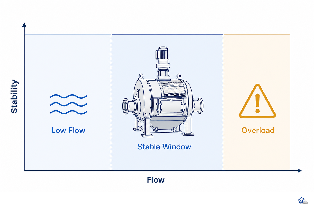
Pressure-screen capacity planning begins with a dry-solids and hydraulic balance, and ends when the operating condition has stabilized on the validated machine curve for its designed duty. Factors include throughput, feed flow rate, consistency, aperture and open area, passing velocity, reject balance, furnish type, contaminant load, accept-quality limits, pressure range, and motor constraints.
Apply the calculation process as follows: Define dry-solids feed rate; translate consistency to wet-based flow; portion dry-solids to accept and reject streams; determine that hydraulic flow and effective open area are present; verify that quality, pressure, power, and stability are at or within OEM and commissioned limits. Don’t allow basket diameter to be translated into assured output rate.
| Input or step | Illustrative value | Calculation | Decision limit |
|---|---|---|---|
| Dry-solids feed | 120 dry t/d | Defined production input | Confirm actual grade and furnish |
| Feed consistency | 2.0% | 120 / 0.02 = 6,000 t/d slurry | Use measured, representative consistency |
| Approximate density | 1.0 t/m³ | 6,000 / 24 = 250 m³/h | Replace with the mill’s engineering basis |
| Mass reject | 15% | 120 x 0.15 = 18 dry t/d | Verify reject flow and consistency separately |
| Dry accept | 102 dry t/d | 120 – 18 = 102 dry t/d | Accept quality still has to pass |
That calculation doesn’t prove the basket will operate at 250 m³/h. The North Carolina State screening review treats consistency, reject rate, pressure difference, slot velocity, and temperature as coupled variables. A conclusive statement therefore requires effective open area, aperture shape, acceptable slot or hole velocity, rotor orientation, operating pressure, motor drive power, furnish response, and target quality. Both low consistency and medium consistency are duty categories, not transferable setpoints, unless they are linked to actual operating conditions.
Engineering Note
During one TAPPI mill trial, feed consistency was 1.1-1.3% and slot velocity was 1.3 m/s. Researchers held volumetric reject at 14%; mass reject moved from 19% to 24% as rotor speed decreased, and a corrected 22.5% mass-reject basis was used for the rotor comparison. At 13.3 m/s, the setup remained stable; the test screen plugged at 11.2 m/s. That comparison also showed about 42% lower power at retained capacity. These are test conditions, not tolerances or recommended set points. Use the installed model’s manual, drawings, commissioning record, and approved change procedure.
Key takeaway: Use a mass balance to estimate operating capacity. Only the OEM curve and actual machine commissioning experience will validate capacity operating parameters for the selected basket, rotor, furnish, and desired quality level.
Use a Controlled Startup, Stabilization, and Shutdown Sequence
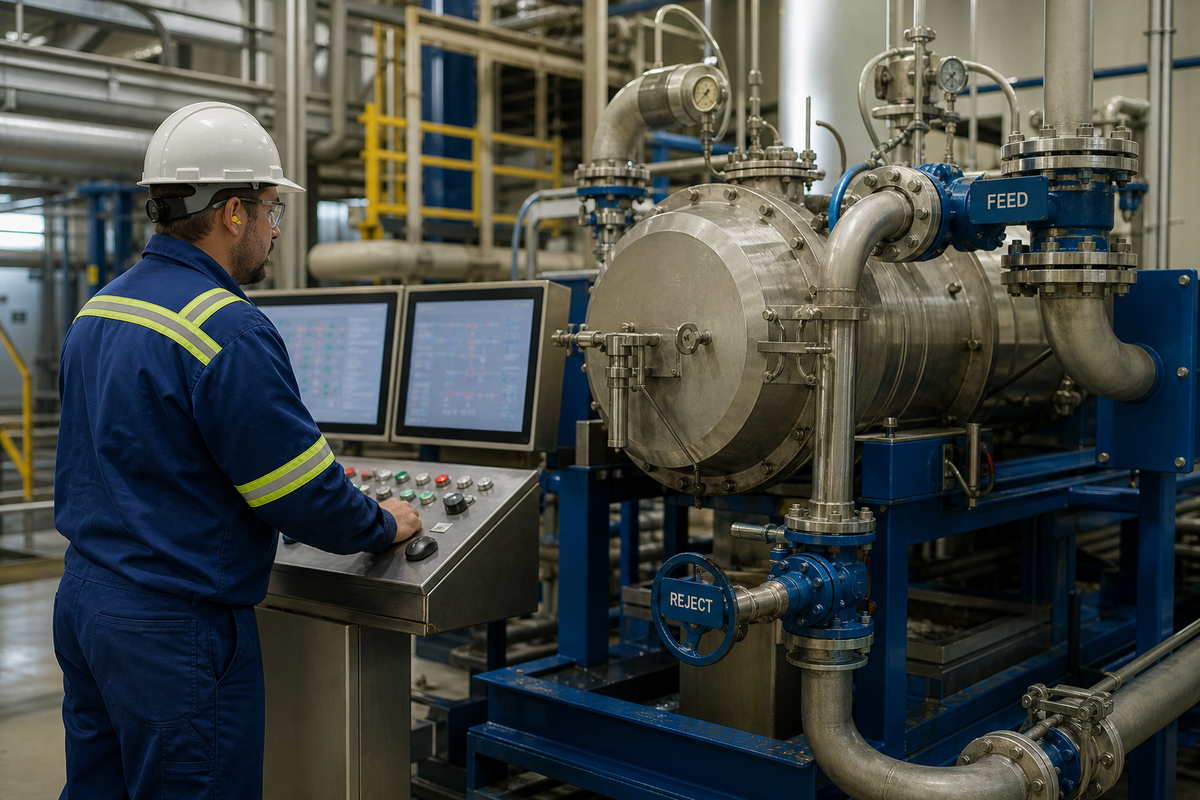
During a controlled start-up, bring utilities, diluents, discharge streams, rotor, feed, and motor drive online sequentially to match the model’s installed condition and operating procedures. Use the start-up as a system-wide operating review, but it isn’t a replacement for the OEM valve sequence, interlocks, alarms, site standard operating procedure, or lockout procedures.
- Verify readiness — confirm the vessel is closed, guards are fitted, instruments are available, discharge paths are ready, and the approved pre-start checklist is complete.
- Establish utilities — place seal water, dilution, lubrication, and supporting systems in the machine-specific condition.
- Start the wet system — follow the OEM procedure for filling, venting, rotation, and minimum-flow protection.
- Ramp the feed — increase stock gradually while watching flow, pressure, differential pressure, motor load, vibration, reject, and accept quality.
- Hold for stabilization — record a same-duty baseline only after the readings and quality response settle inside approved limits.
- Stop under control — reduce load, clear stock, flush, and stop in the documented model sequence; use the abnormal-stop procedure when a stop condition appears.
Hold the start-up ramp on increasing differential pressure, fluctuating feed rate, unexpected change in motor load, abnormal machine vibration, plugging in the reject path, or a departure from quality limits. Don’t attempt to bypass an interlock to complete the sequence. Don’t perform a normal shutdown if isolation is intended.
For covered servicing in the United States, OSHA 29 CFR 1910.147 requires documented hazardous-energy control, treatment of stored energy, and verification of isolation. Other jurisdictions and the site may impose different or additional requirements.
Use the applicable machinery-safety and condition-monitoring framework when a pressure screen is designed, modified, commissioned, guarded, or serviced. The references below define general methods and safeguards; they do not supply pressure-screen operating limits, basket clearances, alarm values, or a substitute for the OEM manual and the site’s legal requirements.
| Reference | Use in a pressure-screen review | Boundary |
|---|---|---|
| ISO 12100:2010 | Structure machinery hazard identification, risk estimation, and risk reduction throughout the machine life cycle. | General design methodology; it does not define model-specific operating or maintenance limits. |
| ISO 14118:2017 | Address unexpected start-up from electrical, hydraulic, pneumatic, stored-energy, or external sources during intervention. | The required machine-specific means still come from risk assessment and applicable site or type-C requirements. |
| ISO 14120:2015 | Guide the design and selection of fixed or movable guards against mechanical hazards. | It does not cover interlocking-device requirements. |
| ISO 13849-1:2023 | Frame the design and integration of safety-related control-system parts that perform safety functions. | It does not choose the required safety functions or performance level for a particular screen installation. |
| ISO 13850:2015 | Review the emergency-stop function and its design principles as part of the machine safety concept. | An emergency stop does not replace isolation, guarding, or a controlled shutdown procedure. |
| ISO 20816-1:2016 | Provide a general framework for measuring and evaluating machine vibration during monitoring and acceptance testing. | Actual sensor positions, machine class, alert limits, and acceptance criteria must be defined for the installed equipment. |
Key takeaway: Use a staged ramp to confirm stable machine operation, but execute each step according to current site and OEM-specific operating procedures.
Read Screen Basket and Rotor Wear Before Pulp Quality Drifts
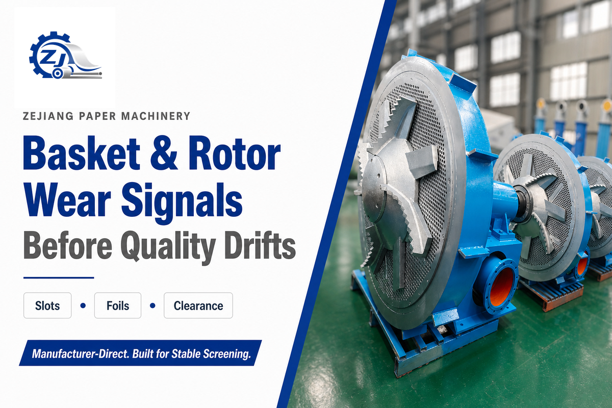
Condition of the basket and rotor is best assessed with trend evidence and a clean visual inspection. BioResources research on pressure-screen plugging shows that aperture restriction can develop through transitional plug-and-release behavior, which is why deposit patterns should be separated from permanent wear. Deposits reduce open area; worn slots or holes can alter separation; coating removal can accelerate basket abrasion; rotor deposits or damage can shift pulses; and out-of-tolerance clearance affects capacity, power, plugging, and fiber treatment.
| Observed condition | Possible process effect | Confirming evidence | Next check |
|---|---|---|---|
| Soft or hard deposits | Lower open area, rising pressure loss, capacity loss | Deposit map, flow and DP trend | Identify chemistry, furnish, and cleaning compatibility |
| Worn slots or holes | Contaminant carryover or changed fractionation | Measured opening versus drawing | Review repair, recoat, or replacement feasibility |
| Coating or profile loss | Accelerated wear or reduced separation response | Surface inspection and dimensional survey | Ask for model-specific acceptance criteria |
| Rotor deposits or damage | Uneven pulse, vibration, plugging, power change | Rotor map, balance evidence, trend history | Check cause before cleaning or repair |
| Contact or rubbing marks | Heat, vibration, metal damage, unstable load | Witness marks, bearing and clearance checks | Escalate before restart |
| Seal or bearing distress | Leakage, temperature, vibration, misalignment | Lubrication, temperature, vibration, play | Follow the component manual |
As a supporting case, the documented Lessebo Bruk color-fiber complaint preceded pulp stringing, repeated web breaks, and obvious basket wear in equipment that had been in service between rebuilds. This reinforces the importance of trend evidence to justify opening the machine, but an opened and cleaned piece of equipment only establishes its current physical condition. It doesn’t establish that basket wear caused an observed quality shift.
In his 2025 Paper Advance article, Jens Heymer describes the cylinder and rotor as core screening components, with rotor type, speed, and gap to the cylinder considered application-specific. While Zejiang’s screen baskets and refiner plates page provides background on replacement parts, actual dimensions and condition take precedence over catalog data for ordering and fit-up.
Bottom line: If the equipment can’t be inspected for cleanliness and measured accurately against the design drawing, isolate deposit removal from other repairs or replacements.
Use the 9-Symptom Pressure Screen Diagnostic Matrix
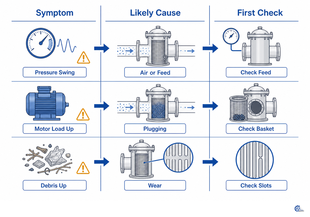
Shown below, the 9-Symptom Pressure Screen Diagnostic Matrix progresses from symptom to supporting evidence, initial action, and escalation criterion. It guides the next investigative step, but doesn’t authorize a setpoint change, maintenance task, or machine restart.
| Symptom class | Probable cause classes | Verify first | First safe response | Escalate when |
|---|---|---|---|---|
| 1. Rising differential pressure | Blinding, higher feed, higher consistency, accept restriction | Both transmitters, flow, consistency, valve positions | Hold or reduce the approved ramp and protect reject flow | Trend persists after process conditions are restored |
| 2. Falling differential pressure | Lower feed, instrument error, bypass, enlarged aperture, damage | Feed/accept flow, transmitter zero, accept quality | Validate measurement and mass balance | Quality worsens or flow cannot explain the drop |
| 3. Unstable pressure | Pump cycling, chest level, valve hunting, intermittent plugging | Time-aligned pump, level, flow, and DP trends | Stabilize the feed interface under the approved procedure | Cycling remains with a steady feed command |
| 4. Capacity loss | Reduced open area, changed furnish, reject restriction, low feed | Dry-solids balance, consistency, DP, reject condition | Return to the validated duty and inspect the flow path | Demand exceeds the documented operating window |
| 5. Rising motor load | Hydraulic load, deposits, rubbing, bearing or rotor concern | Flow, pressure, vibration, temperature, and sound | Stop escalation; use the abnormal condition rule | Contact, heat, or mechanical distress is suspected |
| 6. Abnormal vibration | Deposit imbalance, damage, looseness, bearing, contact | Route, speed, spectrum/trend, temperature, visual condition | Apply the site’s vibration escalation boundary | New vibration accompanies load, heat, or noise |
| 7. Excessive reject | Valve/dilution change, higher debris, conservative recovery setup | Reject flow, consistency, contaminant and fiber content | Reconcile removal benefit against fiber loss | Recovery loss persists at the approved quality target |
| 8. Fiber loss in reject | Reject balance, aperture/furnish response, recovery-stage problem | Representative reject sample and downstream recovery | Protect accept quality while reviewing the mass balance | Yield cannot be recovered without quality failure |
| 9. Accept-quality drift | Worn openings, bypass, changed furnish, upstream overload | Lab trend, basket condition, upstream contaminant load | Protect downstream production and retain samples | Physical damage or duty mismatch is indicated |
Plugging can behave as a transition rather than a clean on/off event. Research published in 2024 by BioResources describes intermittent plug-and-release behavior and hysteresis near the operating limit. Pilot work published in 2025 found that pressure-pulse variability rose while pulse magnitude fell before aperture plugging. Its proposed indicator is a research direction, not a production alarm threshold.
One of the most common errors seen in the field is to increase reject or add dilution every time the differential pressure (DP) goes up. This can mask the true trend, wash away the fiber, or push the problem down the line. Preserve the time-aligned evidence first, and then verify the instrument, the hydraulic system, the reject stream, and the condition of the machine.
Bottom line: Verify the symptom with supporting evidence before adjusting the machine. Trend evidence suggests where to look, but physical evidence confirms what to do.
Plan Condition-Based Maintenance and Clean-or-Replace Decisions

Condition-based maintenance combines shift trend data, planned inspections, shutdown measurements, and model-specific criteria. A BioResources pilot study on incipient plugging found changes in pressure-pulse behavior before aperture plugging under its test conditions, supporting a trend-led inspection trigger rather than a universal calendar interval. Time-based scheduling provides opportunities for data collection, but it doesn’t by itself justify cleaning or replacement.
Do
- Trend flow, pressure, power, vibration, reject, and quality together.
- Photograph and map deposits before cleaning.
- Measure openings, profile, and clearance against the current drawing.
- Record repair scope, material, coating, and post-work checks.
- Correct the process cause before restart.
Don’t
- Use a universal cleaning interval.
- Choose chemistry without material compatibility.
- Grind or open slots to recover capacity.
- Reuse a damaged rotor or basket without acceptance evidence.
- Enter or open the vessel before verified isolation.
Confirm basket condition before cleaning if deposits can be removed safely with an approved method, substrate integrity can be maintained, and the aperture won’t change materially. Reinspect it afterward for slot wear, coating damage, contact marks, or other defects previously hidden by deposits. If geometry or structural integrity has changed and can’t be restored within established specifications, repair or replace the basket.
Valmet’s screen-basket service page emphasizes condition inspection and aperture measurement, while the Paper Advance article covers wear control in its prevention, operation, material, and design categories. Both point toward a condition-led approach rather than one-size-fits-all time intervals. Longer life follows from verified condition, fit, and operating control rather than a universal calendar rule.
Takeaway: Clean for condition, measure before deciding, and trace every call for replacement to proof of the installed equipment meeting its acceptance criteria.
Check Integration and Utility Requirements Before Blaming the Screen
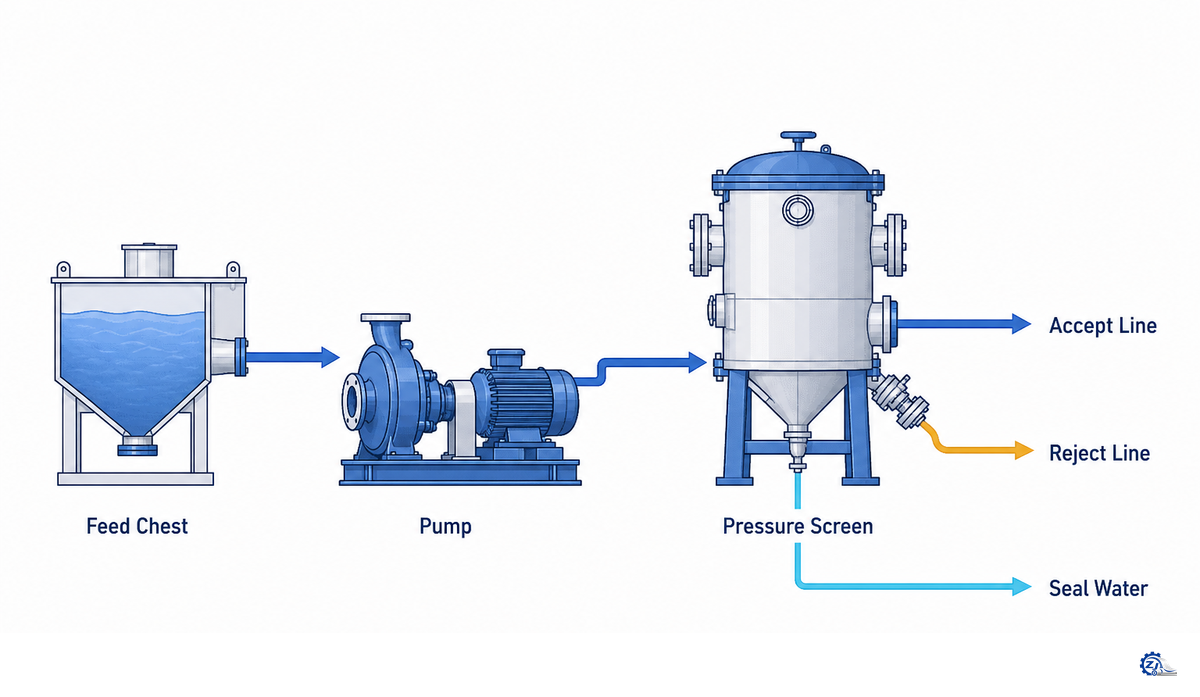
Screen behavior often points to other issues in stock preparation.
Before blaming the basket or the rotor, review the pulper debris load, cleaner efficiency, feed-pump stability, chest agitation, dilution, reject load, downstream demand, controls and utilities. The North Carolina State pressure-screen review treats consistency, reject rate, pressure difference, slot velocity, and temperature as linked variables, reinforcing the need to test interfaces before assigning the fault to one component.
| Interface | Screen symptom it can imitate | Evidence to collect | Boundary decision |
|---|---|---|---|
| Pulper / deflaker | Higher reject, plugging, quality drift | Furnish, debris, flake size, batch timing | Correct feed preparation before resizing the screen |
| Cleaner stage | Abrasive wear or contaminant carryover | Cleaner feed/reject condition and density response | Restore cleaner duty before blaming apertures |
| Stock pump | Pressure cycling and capacity loss | Pump speed, suction, chest level, flow trend | Stabilize the feed source first |
| Chest agitation / dilution | Consistency swings and intermittent blinding | Mixer status, consistency samples, dilution flow | Fix mixing and measurement repeatability |
| Reject loop | Thickening, fiber loss, pressure instability | Reject flow, consistency, dilution, recovery path | Clear or rebalance the loop under procedure |
| Refiner / downstream demand | Accept restriction, altered freeness or quality response | Downstream valve, level, flow, grade target | Separate screen capacity from downstream demand |
| Controls / instruments | False DP, valve hunting, unexplained load shift | Calibration, impulse lines, signal timing, command/feedback | Validate the measurement chain |
| Utilities / access | Seal, bearing, cleaning, or maintenance failure | Water, air, power, drains, lifting and isolation access | Correct infrastructure before repeated intervention |
Use the site’s pulping equipment guide to position the issue in the broader line.
Inspect the stock cleaner, pulp pump and agitator, and paper pulper interfaces as their trends correlate with the screen. The pulping line interface risk check can structure the transition.
Zejiang Paper Machinery’s scope covers paper machines, pulp processing equipment, spare parts, and mill projects. That scope supports a review of machine interfaces, but it is no substitute for a P&ID, cause-and-effect narrative, utilities list, and site-specific data.
Takeaway: When pressure, flow, reject, or quality trends track an upstream or downstream variable, investigate the interface prior to making a change to the screen.
Know When the Evidence Calls for an Equipment-Scope Review
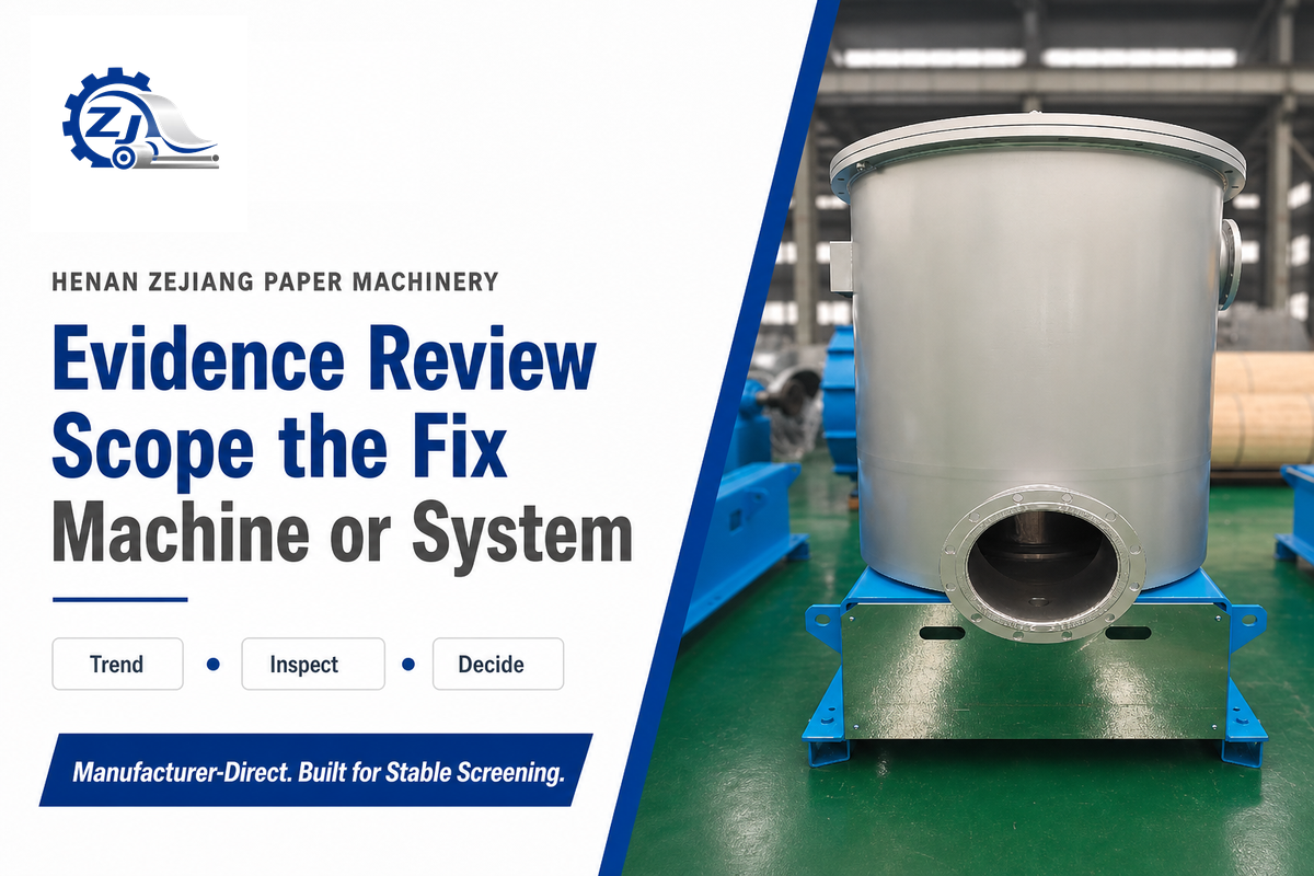
Transition from process-level correction to an equipment scope evaluation when validated duty can no longer be maintained after instruments and interfaces have been confirmed. BioResources research on screening limits documents transitional and hysteretic behavior near plugging. That behavior makes a single pressure excursion weak evidence for replacement on its own; confirm a repeatable trend and physical condition first. Repeated mechanical contact, irreparably deformed basket geometry, a motor or hydraulic-drive constraint, operation outside the design envelope, or a changed furnish and quality target can trigger further assessment.
Assemble a complete evidence package comprising model/serial, duty location, P&ID, basket specs, rotor configuration, input/output flows and consistencies, pressure, motor data, vibration history, furnish, contaminants, quality target, images, measurements, maintenance logs, and the specific failure profile. Sufficient information helps an engineer differentiate among cleaning or repair, control-system work, process re-engineering, and equipment replacement.
Need a model and specification review?
Use Zejiang Paper Machinery’s pressure screen models and specifications page for the commercial selection path for your project. Send the evidence packet above so the discussion starts with duty, furnish, hydraulics, quality, and installed constraints rather than a capacity label alone.
Takeaway: Support your escalation with evidence. A useful RFQ explains current duty and performance boundaries before requesting equipment selection or pricing.
FAQ: Pressure Screen Questions
What is a pressure screen?
A pressure screen is a closed pulp-screening vessel that separates usable fibers from contaminants through basket holes or slots while stock moves under pressure in stock preparation.
A pressure screen is a closed screening vessel used in pulp and paper stock preparation. Pumped stock enters under pressure, usable fibers pass through holes or slots in a basket, and larger contaminants leave through the reject path. A rotor produces pressure pulses that help keep apertures open. The exact flow direction and operating window depend on the screen design, furnish, and duty.
How do you calculate pressure screen capacity?
Calculate the dry-solids and hydraulic duty, then validate aperture, open area, pressure, power, furnish, reject, and quality limits against the OEM curve and commissioning record.
Capacity can’t be confirmed from basket diameter alone. Define feed flow and consistency, aperture size and effective open area, furnish and contaminant load, reject rate, required accept quality, and the allowable pressure and motor-load window. Complete the dry-solids and hydraulic balance, then compare the result with the manufacturer curve and commissioned same-duty baseline. No universal capacity coefficient was found in the reviewed evidence.
What is the pulp screening process?
Pulp screening separates acceptable fibers from contaminants by passing pumped stock through basket apertures while retained material moves through a reject and recovery path for further treatment.
Pulp screening separates acceptable fibers from contaminants according to size, shape, and flexibility. Stock is pumped to a coarse or fine screening stage; fibers that fit the aperture pass to the accept side, and retained material moves toward reject treatment. Multiple stages may recover useful fiber while controlling contaminant recirculation. The correct arrangement depends on furnish, quality target, and the surrounding stock-preparation system.
How do you stop a pressure screen basket from blinding?
Verify instruments and same-duty trends first, then inspect feed consistency, dilution, reject flow, contaminant loading, rotor action, and basket condition before selecting an OEM-approved cleaning method.
First confirm that the pressure trend is real and not an instrument or valve-position problem. Compare feed consistency, dilution, reject flow, motor load, rotor condition, and contaminant loading with the commissioned baseline. If the vessel must be opened, follow the site’s isolation procedure and map the deposit pattern before cleaning. Repeated blinding calls for a root-cause review of furnish, hydraulics, aperture condition, and rotor action rather than another blind setpoint change.
What consistency does a pressure screen run at?
There is no single consistency for every screen; the permitted range depends on duty, rotor and basket design, furnish, separation target, and the manufacturer’s validated operating point.
Use the installed model manual and commissioning record. Coarse, fine, fractionation, broke, and approach-flow duties don’t share one transferable consistency range. A published vendor band can help form a question, but it can’t replace a duty-specific curve and mill test.
What does the rotor do in a pressure screen?
The rotor creates local pressure pulses and sweeping action near the basket so fibers can pass while the aperture surface resists mat buildup during normal operation.
Rotor geometry, speed, clearance, and wear can affect capacity, plugging, power, fiber treatment, and screen performance. Use model-specific settings because a rotor change also changes the local hydraulic condition and plugging margin.
What is a good strategy for unplugging a pressure screen?
Classify the plugging pattern, stabilize or stop under the approved procedure, isolate hazardous energy before access, preserve deposit evidence, and correct the verified cause before restart.
Treat plugging as a symptom. Verify instruments, compare current readings with the stable baseline, and inspect reject flow and upstream contaminant load. After approved isolation and safe access under the applicable hazardous-energy control procedure, record where deposits formed, what they contain, and whether the basket or rotor shows wear. Choose cleaning methods from the OEM manual and material-compatibility guidance. If deposits recur, review furnish, dilution, reject handling, rotor action, aperture condition, and screen duty together.
Where is a pressure screen placed in a paper mill?
Placement follows the screening duty, so a pressure screen may serve coarse screening, fine screening, fractionation, broke treatment, or machine approach flow within stock preparation.
The correct location is defined by incoming contaminant load, required accept quality, recovery stages, pumps, cleaners, refiners, and downstream demand. Record the duty before comparing pressure, reject, or capacity data with another installation.
Review Method and Limitations
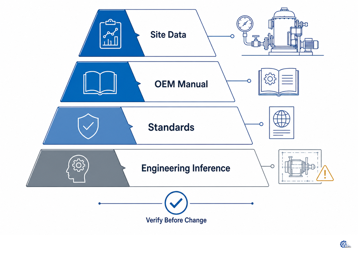
This guidance was drawn from academic theses, an OEM-tested mill trial, recent OSHA documentation, vetted plugging studies, OEM field literature, trade press analysis, and Zejiang’s validated scope of equipment; it doesn’t include customer operating results, an implied universal parameter range, or a fabricated first-person account.
Exact pressure, consistency, rotor speed, clearances, slot width, reject levels, vibration, cleaning parameters, and replacement criteria differ depending on the specific model, furnish, grade, application, and established mill protocols. This article should help organize information; use your mill controls and OEM technical specifications for operating and maintenance decisions.
Turn the trend history into an engineering review
Send Zejiang Paper Machinery the duty description, flows, consistencies, pressures, reject balance, motor and vibration trends, furnish, quality target, basket and rotor details, and inspection evidence. The team can then review whether the next step belongs to process correction, parts, repair, or equipment scope.
Related Articles
References & Sources
- North Carolina State University, pressure-screen separation and rotor-pulse research thesis.
- Library and Archives Canada, experimental and numerical pressure-screen rotor research.
- TAPPI, mill trial on rotor speed, power, stability, and removal.
- U.S. Occupational Safety and Health Administration, 29 CFR 1910.147: The Control of Hazardous Energy.
- BioResources, Detection of Incipient Pulp Screen Plugging.
- BioResources, Understanding the Limits of a Screening Operation, Part 1.
- Paper Advance, technical review of screening and refining wear components.
- International Organization for Standardization, ISO 12100:2010 machinery risk assessment and risk reduction.
- International Organization for Standardization, ISO 14118:2017 prevention of unexpected start-up.
- International Organization for Standardization, ISO 14120:2015 fixed and movable guards.
- International Organization for Standardization, ISO 13849-1:2023 safety-related control-system parts.
- International Organization for Standardization, ISO 13850:2015 emergency-stop function.
- International Organization for Standardization, ISO 20816-1:2016 machine-vibration measurement and evaluation.

![Refiner Plates & Screen Baskets [Complete Guide]](https://zjpapermachine.com/wp-content/uploads/2026/07/refiner-plates-screen-baskets-guide-featured-150x150.png)
![Doctor Blade: Types, Materials & How It Works [Guide]](https://zjpapermachine.com/wp-content/uploads/2026/07/doctor-blade-guide-featured-1-150x150.png)
![Pulping Equipment: How Paper Pulping Works [Guide]](https://zjpapermachine.com/wp-content/uploads/2026/07/pulping-equipment-guide-featured-150x150.png)