
Get in touch with Zejiang Paper Machinery Company


Updated July 2026
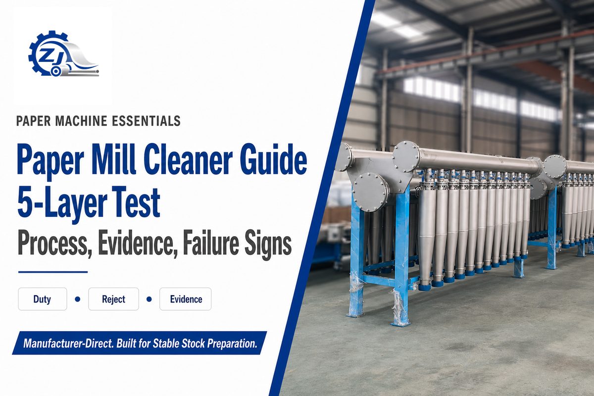
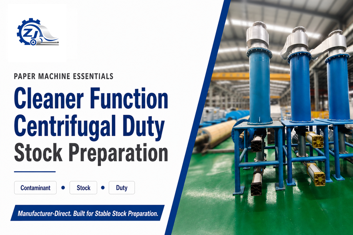
A Paper Mill Cleaner is a centrifugal separator used in pulp-stock preparation. It isn’t a cleaning chemical, a fabric washer, or a mill-surface cleaning system. Rotating stock sends selected contaminants along a different path from useful fiber, then divides the flow into accept and reject streams.
That definition sounds simple; operating decisions aren’t. Material separates consistently only when it develops a repeatable physical advantage under the actual stock, flow, pressure, geometry, and stage conditions. This guide shows how to judge that boundary, read the operating evidence, troubleshoot without jumping to a cause, and decide when a system review is justified.
Scope boundary
This article owns the process guide: mechanism, contaminant limits, cleaner duty, diagnostics, maintenance boundaries, reject recovery, and system integration. Equipment families, configuration details, manufacturing support, and quotations remain on the paper mill cleaner configurations page.
What a Paper Mill Cleaner Means in Stock Preparation
Paper-stock cleaning is one operation within a wider separation train. A technical review hosted by NC State University distinguishes three physical bases: screening and washing act mainly on particle dimensions, centrifugal cleaning is density-led, and flotation acts on surface properties. That distinction explains why “cleaner” shouldn’t be read as “removes every unwanted material.”
Inside a stock-preparation line, the cleaner receives suspended fiber, water, and contaminants. Tangential inlet flow creates rotation. Material that behaves differently in that field migrates toward another outlet path. Accepted stock moves forward; the reject carries concentrated unwanted material along with water and, usually, some usable fiber. What reports to either stream depends on much more than the equipment name.
Within the system, a cleaner may operate alongside a pulper, coarse separation, pressure screening, deinking, pumps, agitators, refiners, and approach-flow equipment. See the pulping equipment hierarchy for that context. No cleaner can correct a contaminant that should have been removed by an aperture, flotation bubble, washing step, or upstream coarse trap.
Terminology varies across the pulp and paper industry. Supplier listings may call the unit a stock cleaner, pulp cleaner, density cleaner, hydrocyclone, or even a slag remover. In papermaking, “slag” is a loose translation for dense reject or heavy impurities, not a precise contaminant class. This guide uses paper mill cleaner for centrifugal equipment and reserves mill cleaning for housekeeping or surface-cleaning work. In paper and pulp sourcing language, low density cleaner and HD cleaner can appear beside generic cleaning solutions or purification claims; none of those labels defines duty without the process boundary.
Key takeaway
A paper mill cleaner is a centrifugal stock separator. Its value depends on whether the target contaminant behaves differently from useful fiber under the actual process duty.
How Centrifugal Cleaner Separation Works
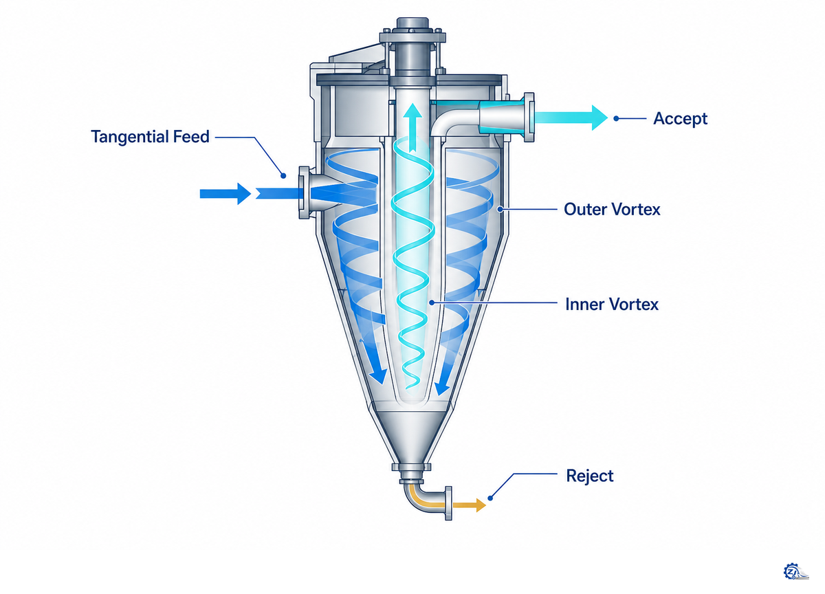
Feed enters tangentially and forms a primary vortex along the cleaner body. Secondary internal flow returns toward another outlet. Inlet geometry, the vortex finder, air core, mantle, cone, accept opening, and reject opening shape those paths. Pressure supplies the energy, but pressure alone doesn’t tell you where a particle will go. The inflow, cone taper, low pressure area, and accept/reject exit geometry interact, so a label can’t predict the split.
Particle motion reflects competing effects. Density changes the response to centrifugal force; size changes the force-and-drag relationship; shape affects orientation and resistance. Flat films, flexible fibers, grit particles, wax fragments, and adhesive specks can behave differently under the same broad label. Stock consistency, viscosity, fiber-network effects, residence time, outlet geometry, and turbulence alter the result again.
That’s why “heavy goes out, fiber stays in” is only a starting model. It explains why dense grit and metal can be plausible targets, but it can’t predict selectivity, fiber loss, or removal on its own. Ask instead: does this particle maintain enough separation advantage from useful fiber under this cleaner’s feed and flow conditions?
Cleaner banks add another layer. Early stages may prioritize contaminant removal, while later stages recover fiber from earlier rejects. Every recovery step changes mass flow and may return contaminants with good fiber. Stage order, dilution points, and reject destinations matter as much as the behavior of one cone.
Use the Separation Boundary Matrix to Match Contaminants to Processes
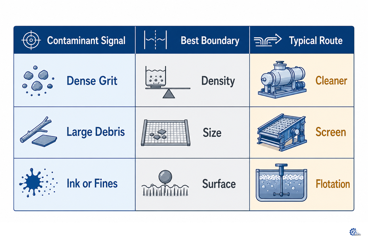
Start with contaminant behavior, not a catalogue label. Use the table below as a process-boundary map. “Plausible” means the material may have a useful centrifugal advantage. “Conditional” means tests and mill evidence are needed. “Another process” means the primary mechanism is commonly better matched elsewhere.
| Contaminant type | Behavior to test | Cleaner fit | Likely companion process |
|---|---|---|---|
| Sand and mineral grit | Dense, abrasive particles with a repeatable slip response | Plausible heavy-cleaner target | Upstream coarse protection and reject washing |
| Metal fragments | High density, but size may threaten upstream equipment | Plausible after coarse protection | Ragger, trap, coarse screen, or magnetic protection |
| Glass | Dense and abrasive; fragmentation changes size | Plausible with duty testing | Coarse separation before fine stages |
| Bark and dense dirt | Mixed shape and density | Conditional | Screening and washing |
| Light plastic | Buoyant or low-density behavior, often deformable | Conditional light-cleaner duty | Coarse or fine screening |
| Foam and polystyrene | Light, compressible pieces | Conditional | Screening plus light-contaminant control |
| Wax and hot-melt fragments | Temperature-sensitive and deformable | Conditional; test actual furnish | Screening, dispersion, or chemistry |
| Pressure-sensitive stickies | Deformable, fragmented, or colloidal | Often weak as a target for cleaner adjustment alone | Fine screening, flotation, dispersion, or chemical control |
| Ink particles | Size and surface properties change after pulping | Selected particles only | Flotation and washing |
| Shives and fiber bundles | Fiber-like shape and aperture response | Poor primary fit | Pressure screening and refining review |
| Dissolved or colloidal material | No stable particle separation advantage | Not a cleaner target by itself | Chemistry, washing, flotation, or water-loop control |
| Useful fiber | Flexible, variable geometry, and network interaction | Material to retain | Reject-stage recovery with contaminant checks |
Process conditions shift this boundary as pulping fragments contaminants, heat softens material, shear changes shape, and dilution alters the fiber network. When surface properties or dispersion dominate, review thickening and deinking equipment instead of forcing an answer through cleaner adjustment alone.
Where Cleaner Duty Changes Along the Stock-Preparation Line
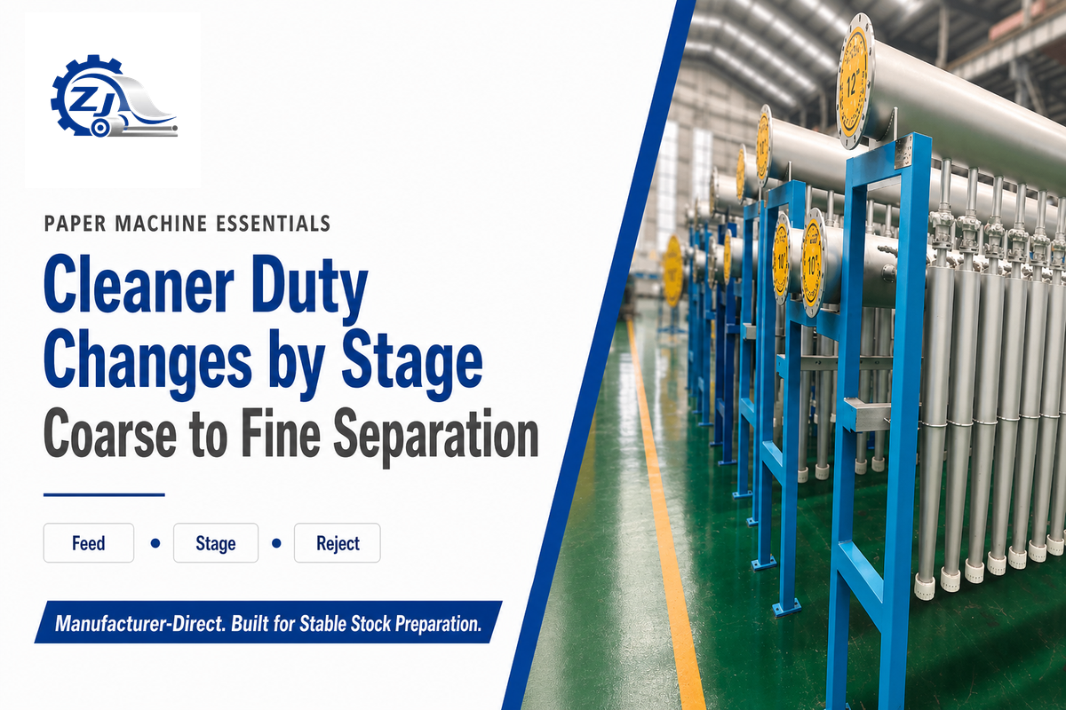
Cleaner duty changes with process position. Early cleaning protects downstream pulp machine equipment from coarse, dense, abrasive material. Fine forward-cleaner duties sit later, where stock slurry is more dilute and smaller contaminants matter. Light-contaminant systems redirect the separation objective. Recovery stages treat a concentrated reject stream rather than the original feed.
In a recycled-fiber pulp mill, waste paper pulping and OCC variability can shift the burden on fine cleaning and subsequent stages, so the cleaning process should be reviewed as a train.
UBC’s lecture supplies useful teaching examples, shown below to illustrate how different those duties can be. They are not Zejiang specifications, selection ranges, or recommended settings. Don’t copy any value without checking the source duty, furnish, cone design, and current OEM documentation.
| Lecture example | Illustrative values | What the example proves |
|---|---|---|
| Forward-flow diagram | 140-200 kPa (20-30 psi); feed 0.6% | One flow arrangement has its own pressure and feed context. |
| Reverse-flow diagram | 140-280 kPa (20-40 psi); feed 1.0% | Changing duty changes the illustrated pressure window. |
| Through-flow diagram | 70-100 kPa (10-15 psi); feed 1.0% | No single “normal pressure” can represent every cleaner type. |
| High-density cleaner example | 2-6% feed consistency; 25-120 cm diameter; 2-6 m height | Earlier duty can involve larger equipment and thicker stock. |
| Medium-density cleaner example | 1-3% consistency; 20-65 cm diameter; 2-6 m height | Labels describe a duty family, not one transferable design. |
| Fine forward-cleaner example | 0.5-1.5% consistency; 7.5-30 cm diameter; 0.6-2.4 m height | Later, finer duty can use a different physical scale. |
The same UBC examples include 2-6 m overall height for high- and medium-density duties and 0.6-2.4 m for fine forward cleaners. Those figures remain lecture examples, not universal dimensions.
For line-level context, compare the duty with the stock-preparation equipment guide and the upstream paper pulper guide. When a mill is ready to discuss actual equipment, the commercial cleaner selection page is the correct handoff.
Apply the 5-Layer Cleaner Boundary Test Before Changing a Stage
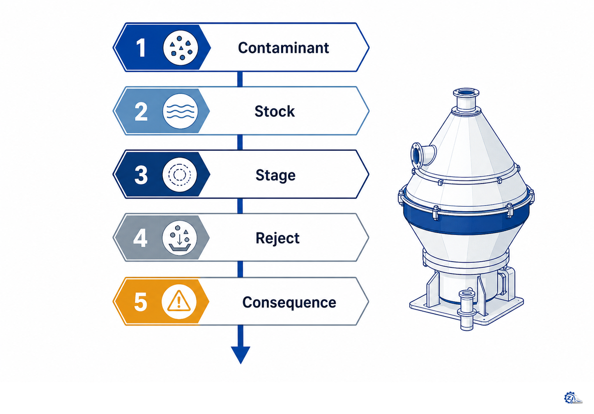
Called the 5-Layer Cleaner Boundary Test, this article’s framework turns a vague complaint into a decision record. Complete all five layers before changing a reject valve, adding cones, replacing a body, or blaming the cleaner for a downstream defect.
| Layer | Evidence to collect | Decision question |
|---|---|---|
| 1. Contaminant | Type, size distribution, shape, density behavior, deformability, and sampling location | Is centrifugal separation physically plausible? |
| 2. Stock | Furnish source, consistency, temperature, freeness, entrained air, and variability | Has the feed changed the particle or fiber behavior? |
| 3. Stage | Process position, cone arrangement, feed/accept/reject readings, and instrument confidence | Is this the right duty and is the stage operating consistently? |
| 4. Reject | Reject volume, reject consistency, contaminant concentration, fiber content, and destination | Is the system removing contamination or moving the loss elsewhere? |
| 5. Consequence | Accept cleanliness, downstream wear, sheet defect, runnability, recovery, and water-loop effects | Did the change solve the mill problem without creating another one? |
Order matters. If the contaminant belongs to screening, no pressure adjustment can turn a cleaner into an aperture. If the stock changed, comparing today’s reject stream with last month’s settings can mislead. If an instrument isn’t trusted, a valve move based on that signal adds uncertainty. Use the pulping-line interface risk check when the evidence points across more than one machine.
The BioResources separation review supports the mechanism boundary behind the first two layers; the remaining layers are this article’s qualified decision framework, not a published standard.
Read Pressure, Flow, Consistency, and Reject as One Evidence Set
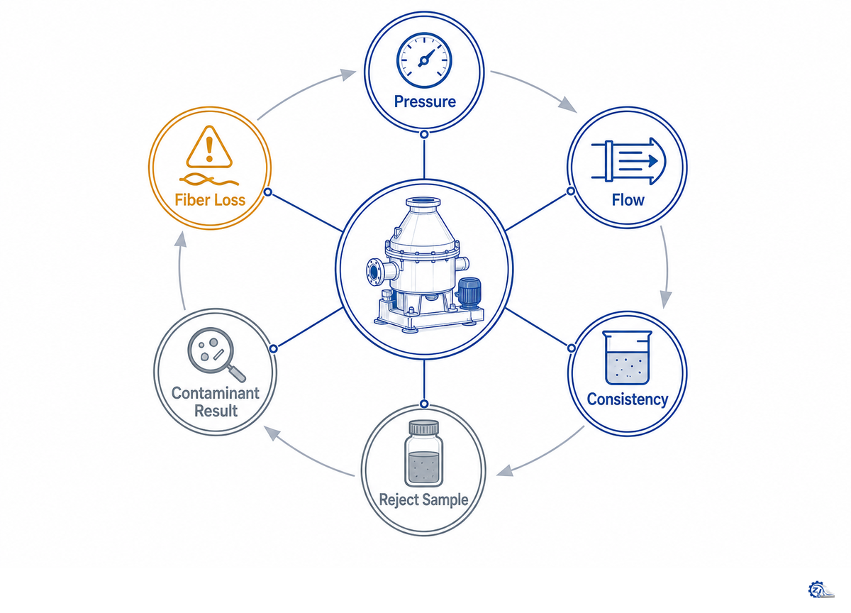
The UBC teaching diagrams pair each cleaner arrangement with its own pressure and feed context: forward, reverse, and through-flow examples use different pressure windows and feed consistencies. They are teaching examples, not universal setpoints.
Read reject data on a declared basis—volume, consistency, and solids—because the same stream can look different under each measure. The UBC light-contaminant example reports those measures separately, so a stand-alone “reject rate” cannot describe fiber loss or contaminant removal.
Use the separation-process review for the physical mechanism boundary and the UBC lecture for scoped teaching examples. Neither supplies a universal setting.
Create a comparable operating window
Cleaner diagnosis becomes unreliable when readings come from different production windows. A feed sample taken before a grade change can’t be compared safely with a reject sample collected after dilution, valve movement, or a cone-bank change. Build one timestamped snapshot instead. Record the running grade, furnish source, production rate, active unit count, pump state, valve positions, and recent operator actions. Collect feed, accept, and reject samples close enough together to represent the same condition.
Instrument confidence belongs in that snapshot. Note the tag number, engineering units, calibration status, sample-point location, and whether a second observation supports the reading. A pressure value can be accurate yet answer the wrong question because the transmitter sits on a shared header or the display shows gauge pressure rather than the differential being discussed. Flow inferred from valve position carries less confidence than a verified flowmeter reading. Where a PLC history is available, align pressure and flow changes with pump state and power consumption; a cost-effective claim about papermaking equipment means little without the same operating window.
Interpret the data as a pattern, not a hunt for one “bad” number. Stable pressure with changing feed consistency suggests a different path from simultaneous pressure, flow, and reject instability. Cleaner accept may look better while total fiber loss rises, or reject may look dirtier simply because less water leaves with it. Pair each reading with mass flow or a downstream consequence whenever instrumentation permits. If the pattern can’t be reproduced, preserve it as an open question instead of changing several variables at once.
| Evidence row | Record together | What it can rule in or out |
|---|---|---|
| Feed pressure | Reading, trend, instrument ID, pump state | Feed-energy change or bad signal |
| Accept pressure | Reading and downstream valve/header state | Changed pressure drop or downstream restriction |
| Reject pressure | Reading, discharge behavior, and destination | Restriction, open path, or unstable discharge |
| Feed flow | Actual flow and active cone count | Loading change or distribution problem |
| Feed consistency | Lab/online result and sampling time | Fiber-network and viscosity change |
| Reject volume | Flow plus valve/nozzle condition | Too little, too much, or intermittent discharge |
| Reject consistency | Reject and feed consistency from matched samples | Thickening and fiber-loss change |
| Freeness and temperature | Matched feed sample and grade/furnish | Stock-property change behind the symptom |
| Contaminant distribution | Feed, accept, reject samples by class and size | True separation change versus visual impression |
| Downstream result | Wear, cleanliness, defect, runnability, and recovery record | Whether the cleaner change solved the plant problem |
Don’t read the worksheet as ten independent alarms. Look for a coherent pattern and verify the instruments before inspection. Feed-flow and mixing changes can also originate around pumps and chests; the pulp pump and agitator guide covers that adjacent interface.
Paper Mill Cleaner vs Pressure Screen: Know the Separation Boundary
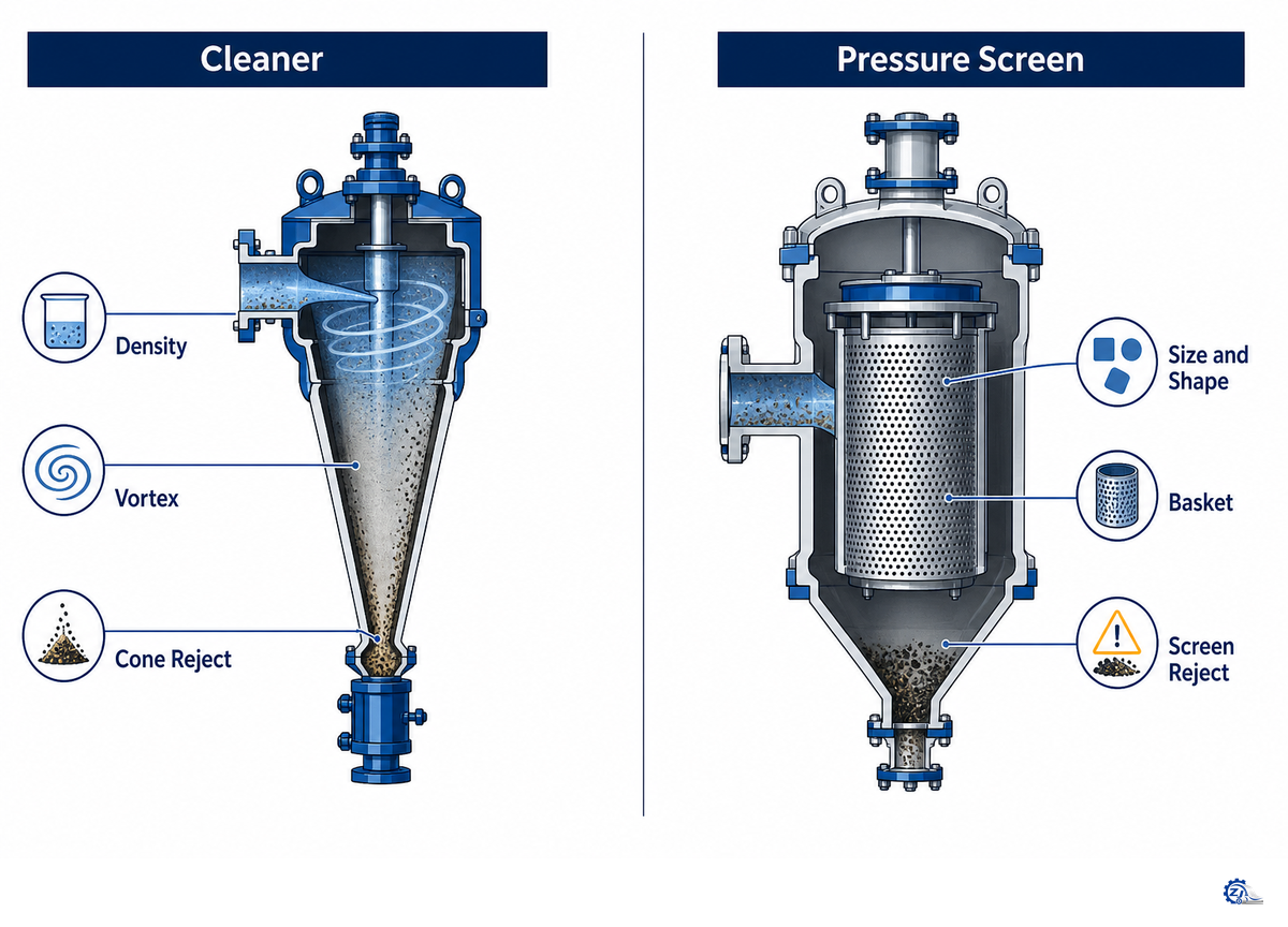
Cleaners and pressure screens may sit close together and still do different jobs. Screens present apertures, so passage depends strongly on size, shape, flexibility, orientation, and basket hydrodynamics. Cleaners create a vortex, and migration depends on each particle’s centrifugal response relative to the surrounding stock.
| Comparison dimension | Centrifugal cleaner | Pressure screen |
|---|---|---|
| Primary separation basis | Vortex-driven particle behavior | Passage or retention at apertures |
| Strong candidate | Material with a stable density/drag advantage | Material distinguishable by size, shape, or flexibility |
| Weak candidate | Fiber-like, dispersed, or poorly differentiated particles | Material that deforms through the aperture |
| Key wear area | Inlet, body, cone, apex/nozzle | Basket, rotor/foil, and clearances |
| Primary readings | Pressure, flow, consistency, and reject behavior | Pressure differential, throughput, reject, and basket condition |
| Common restriction | Reject path or cone obstruction | Aperture plugging or basket loading |
| Fiber-loss question | How much fiber follows reject? | How much good fiber is retained or sent to reject? |
| Stage role | Heavy, fine, light, or recovery duty | Coarse, fine, fractionation, or tailing duty |
| Wrong substitution | Trying to solve an aperture problem with pressure | Trying to solve density behavior with a smaller slot alone |
| System answer | Often used with screening | Often used with centrifugal cleaning |
For more detail on the aperture side, see the pressure screen guide and the related refiner plates and screen baskets page.
Troubleshoot Cleaner Problems in a Safe Order
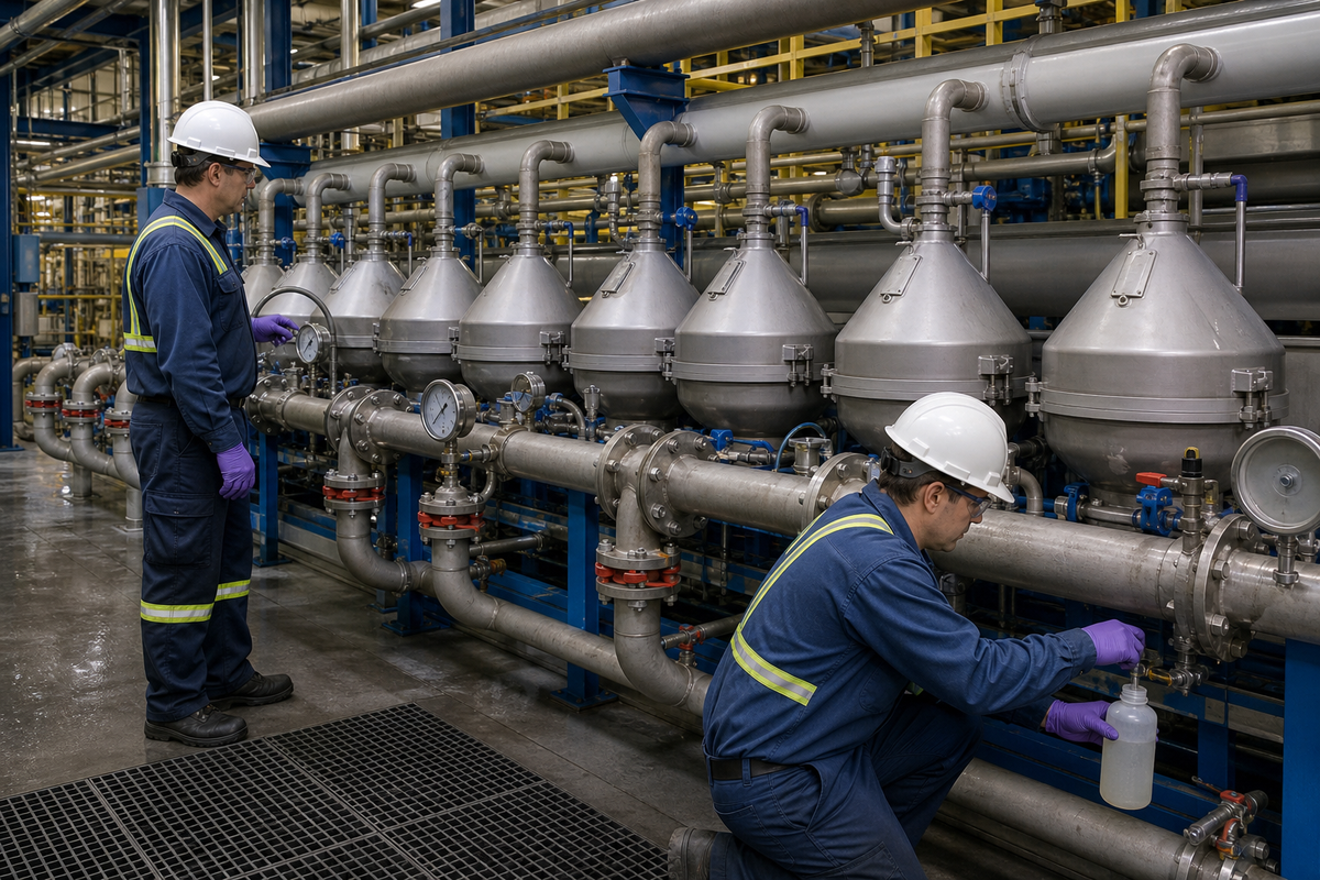
Start the mechanism check with the BioResources particle-separation review. It keeps screening, washing, centrifugal cleaning, and flotation tied to different physical bases, which helps test whether the observed contaminant still fits cleaner duty before a setting or component is blamed.
Symptoms aren’t causes. Low pressure may come from the pump, a valve, a header, excess open area, feed dilution, or a bad transmitter. Unstable reject can indicate restriction, air entry, inconsistent feed, or a control problem. Worsening accept cleanliness may reflect furnish change, duty mismatch, wear, obstruction, or sampling error.
Use a sequence that removes uncertainty before it adds mechanical exposure. Follow the current OEM manual and the site’s energy-control procedure for the exact isolation and access method.
- Define the symptom — record when it began, which grade and furnish were running, and which downstream result changed.
- Verify the signal — check instrument identity, calibration status, units, impulse lines, and agreement with an independent observation.
- Stabilize the feed context — compare pump state, flow, consistency, temperature, freeness, entrained air, and active cone count.
- Inspect the reject behavior externally — observe whether discharge is stable, restricted, intermittent, diluted, or routed to an unexpected destination.
- Compare matched samples — examine feed, accept, and reject for the same contaminant classes and useful-fiber loss.
- Isolate before intrusive inspection — follow the site procedure and OEM instructions before opening, removing, or reaching any pressurized component.
- Change one controlled variable — document the change, its reason, and its consequence across the five boundary layers.
This order prevents a common maintenance error: finding a worn or dirty component and assuming it caused the original complaint. Wear can matter, but evidence has to connect it to flow, separation, reject behavior, and the downstream consequence.
Sampling discipline matters just as much. Mark every container with stream, time, grade, furnish, and active-stage condition before it leaves the floor. Use the same method at feed, accept, and reject points, then classify contamination by more than visual darkness. Particle size, shape, flexibility, apparent density behavior, and useful-fiber content help distinguish a real separation change from a water-balance change. Photographs against the same background and scale create a repeatable record, although they don’t replace a mass balance.
After one controlled change, wait for the stock volume between the change point and sample point to turn over according to the mill’s own process calculation. Sampling too soon mixes old and new conditions; waiting through another unrelated process change adds a different confounder. Record what stayed constant, what moved, and whether the effect appeared in accept quality, reject composition, downstream wear, sheet defects, or runnability. That evidence trail is more useful to maintenance and engineering teams than settings without time context.
Maintain the Cone, Reject Path, and Instruments by Condition
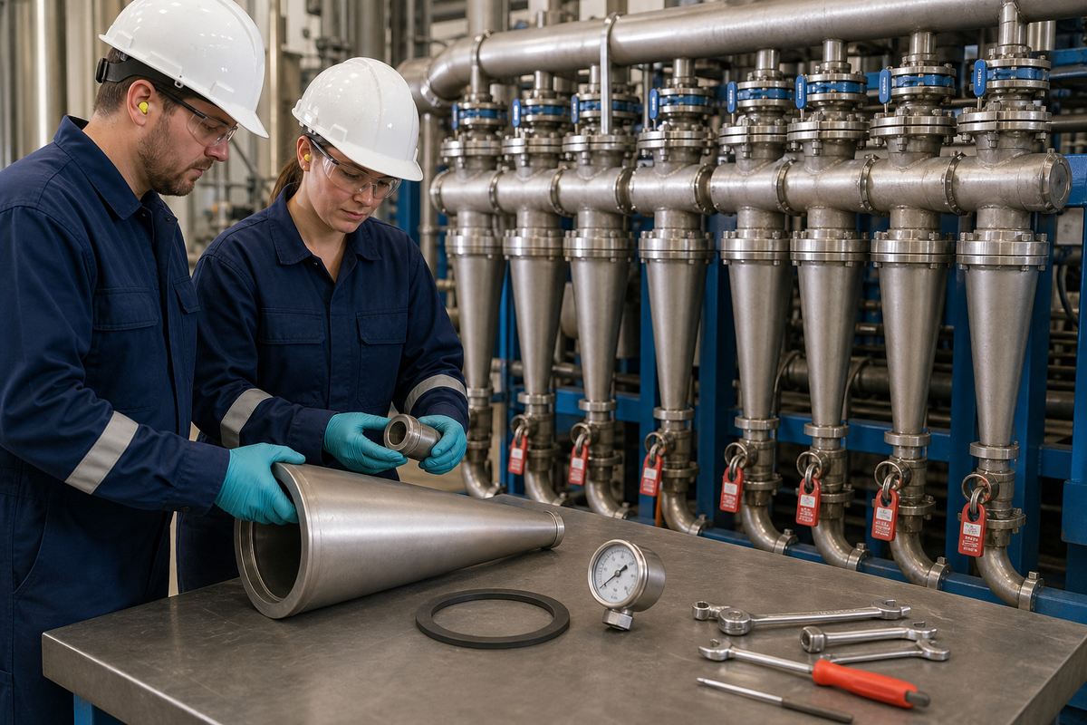
No credible source reviewed for this guide supplied a universal maintenance interval or transferable wear limit. Calendar planning can organize work, but the interval must reflect abrasive load, furnish variability, consistency, duty, body and cone materials, nozzle geometry, pressure behavior, reject stability, and the manufacturer’s instructions. Labels such as “ceramic” or “wear-resistant” don’t create a transferable interval; measured condition and the current OEM limit still govern.
The ISO committee scope for pulp-and-paper machinery safety supports a general safety boundary only; it doesn’t publish a model-specific cleaner interval or wear limit.
Which safety rules govern cleaner inspection?
ISO 12100:2010 supplies general machinery risk-assessment and risk-reduction principles. For U.S. plants, OSHA 29 CFR 1910.147 applies to hazardous-energy control during servicing and maintenance, while OSHA 29 CFR 1910.261 addresses pulp, paper, and paperboard mills. These sources define safety boundaries; none supplies a cleaner setpoint, maintenance interval, or wear limit. The current site procedure and OEM instructions still govern the exact isolation method.
Recovered-material systems add another complication: contaminants wear key components, and raw-material quality can change. Condition evidence is therefore more useful than copying a generic “every three months” recommendation. Record pressure and flow drift, reject instability, repeated plugging, leakage, abnormal vibration or noise, accept cleanliness, fiber loss, and measured component condition.
Do
- Trend instruments and matched samples before shutdown.
- Photograph and measure wear at repeatable locations.
- Record the cone, nozzle, seal, and reject-path condition together.
- Confirm repair results against accept and reject evidence.
Don’t
- Copy an interval from a different furnish or cleaner duty.
- Open a pressurized body to “take a quick look.”
- Replace a cone without checking the reject path and instruments.
- Treat visible wear as proof of the original fault.
Balance Reject Recovery as Furnish Variability Changes
Recovered fiber isn’t a niche operating condition. AF&PA reports that in 2024 the U.S. recycled 60%-64% of paper and 69%-74% of cardboard available for recovery. U.S. mills used 32.7 million tons of recycled paper, compared with 31.3 million tons in 2023; recycled paper represented 44.4% of mill fiber use in 2024, up from 36.6% in 2005 and 37.7% in 2015. Those figures describe the U.S. fiber context, not cleaner efficiency.
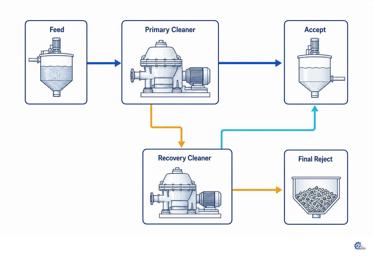
For a mill, the practical issue is variability. Recovery stages can return useful fiber, but they can also return contaminants that haven’t developed a stable separation advantage. Before raising recovery, compare contaminant concentration and fiber mass across feed, accept, reject, recovery accept, and final discharge. “Less reject” isn’t a result if contamination reappears downstream.
One UBC light-contaminant diagram shows feed at 0.6-0.8% consistency. Its illustrated light reject is below 10% of feed flow, below 0.01% consistency, and below 1.0% of feed solids; the heavy reject is shown at 3-8% of feed flow, 1.5-3.0% consistency, and 10-25% of feed solids. These values describe that teaching diagram only. They show why volume, consistency, and solids can’t be collapsed into one reject percentage.
The staged-cleaning discussion in the BioResources review is the authority basis for checking recovery as a system; the UBC numbers remain scoped teaching examples.
| Map node | Hidden bottleneck question | Evidence before action |
|---|---|---|
| Contaminant | Did its size, shape, or surface state change? | Matched particle classification |
| Stock | Did furnish, consistency, temperature, or air change? | Feed history and samples |
| Stage | Is the cleaner operating in the intended duty? | Flow, pressure, active units, and arrangement |
| Reject | Where do fiber and contaminants go next? | Mass balance and routing check |
| Consequence | Did the change improve the downstream requirement? | Quality, wear, runnability, and loss record |
When Evidence Points to a Configuration Review
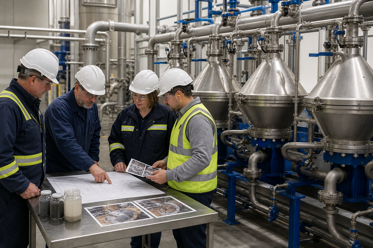
Configuration review is justified when the evidence remains coherent after instruments, feed conditions, reject routing, and maintenance condition have been checked. Review is also warranted when the target contaminant doesn’t fit the installed separation duty, capacity changes have altered loading, or recovery stages repeatedly return the problem. For teams maintaining clean stock, the decision test is whether the change reduces targeted paper defects without hiding fiber loss or recirculating contamination.
The reviewed hydrocyclone patent record illustrates that internal configurations vary; it is design evidence, not proof that one arrangement will perform in a particular mill.
Henan Zejiang Paper Machinery Co., Ltd. is a manufacturer and supplier of paper-making machines, pulp-processing equipment, and spare parts. Its services include design, refurbishment, installation, and technical support for paper manufacturing projects. That company profile supports scope statements only; it doesn’t prove a performance outcome for any mill.
Prepare a review package with the target contaminant, feed and production context, process position, current arrangement, active unit count, matched pressure/flow/consistency data, reject routing, samples, wear observations, downstream requirement, and change history. State the required line capacity, available maintenance labor, measured reject rate and fiber mass balance, and the cleaner product family under review. That package lets plant, maintenance, quality, finance, and purchasing teams weigh downtime, fiber loss, defect exposure, and spare-part scope before a configuration change. Then use the interface risk self-check or review available paper mill cleaner configurations.
Bring evidence, not just a model request
Share the contaminant, furnish, process position, operating evidence, reject path, and downstream requirement. That information lets an engineering conversation begin at the system boundary.
FAQ: Paper Mill Cleaner Questions
What contaminants do pulp cleaners remove?
Pulp cleaners commonly target contaminants that behave differently from useful fiber in a centrifugal field. Depending on duty, that can include sand, grit, metal, glass, dense dirt, or selected light contaminants. Removal isn’t guaranteed by the material name. Density, shape, size, drag, stock consistency, flow conditions, cleaner geometry, and stage arrangement influence where each fraction reports.
What is the difference between high-density and low-consistency cleaners?
These labels describe different process duties and feed conditions, not a universal sizing rule. High-density cleaning is commonly associated with earlier protection against coarse, heavy contamination. Finer or low-consistency stages can serve later duties. Allowable consistency, cone geometry, pressure, reject routing, and capacity depend on furnish and equipment design, so use source values as examples rather than copied settings.
Why is pulp cleaning important before the paper machine?
Cleaning can reduce the contaminant load passed to screens, refiners, pumps, approach-flow equipment, and the paper machine. It may protect wear surfaces and lower defect risk, but it doesn’t replace every separation step. The decision is whether the target contaminant can be removed at that position without excessive fiber loss, unstable reject flow, or contaminant recirculation through recovery.
How often should a paper mill cleaner be maintained?
No fixed interval is safe across installations. Set inspections from furnish abrasiveness, pressure and reject trends, measured wear, and current OEM instructions. Shorten the interval after feed changes, repeat plugging, leakage, or lost cleanliness; extend it only when a documented condition history supports that choice.
What are common signs that a cleaner needs attention?
Watch for unexplained pressure or flow drift, unstable reject, recurring plugs, leakage, abnormal noise, poorer accept cleanliness, and rising fiber loss. Confirm the instruments and feed context before treating any one sign as proof of wear or obstruction.
Can a centrifugal cleaner replace a pressure screen?
Usually not. Cleaners rely on vortex-driven particle behavior, while pressure screens use apertures. Dense grit may present a useful cleaning target; shives, fiber bundles, and deformable contaminants often depend more on size, shape, or flexibility and may require screening. Stock-preparation lines commonly use both operations because neither mechanism covers every contaminant. Before changing either unit, classify the unwanted material, locate where it changes form, compare feed and reject evidence, and verify the downstream requirement. A substitution made from equipment names alone can move the defect or increase fiber loss instead of solving it.
Is a paper mill cleaner suitable for every mill?
No. Suitability depends on furnish, contaminant behavior, process position, available pressure, reject handling, wear risk, and downstream needs. Screening, washing, flotation, dispersion, chemistry, or coarse separation may fit the actual boundary better.
References & Sources
These references support the educational mechanism, duty, operating-control, and recovered-fiber context in this guide. Source-specific values remain scoped to the named teaching example or reporting year. Marketplace listings, unsupported competitor claims, inaccessible forum pages, and unparsed search snippets weren’t used as technical evidence.

![Refiner Plates & Screen Baskets [Complete Guide]](https://zjpapermachine.com/wp-content/uploads/2026/07/refiner-plates-screen-baskets-guide-featured-150x150.png)
![Doctor Blade: Types, Materials & How It Works [Guide]](https://zjpapermachine.com/wp-content/uploads/2026/07/doctor-blade-guide-featured-1-150x150.png)
![Pulping Equipment: How Paper Pulping Works [Guide]](https://zjpapermachine.com/wp-content/uploads/2026/07/pulping-equipment-guide-featured-150x150.png)