
Get in touch with Zejiang Paper Machinery Company


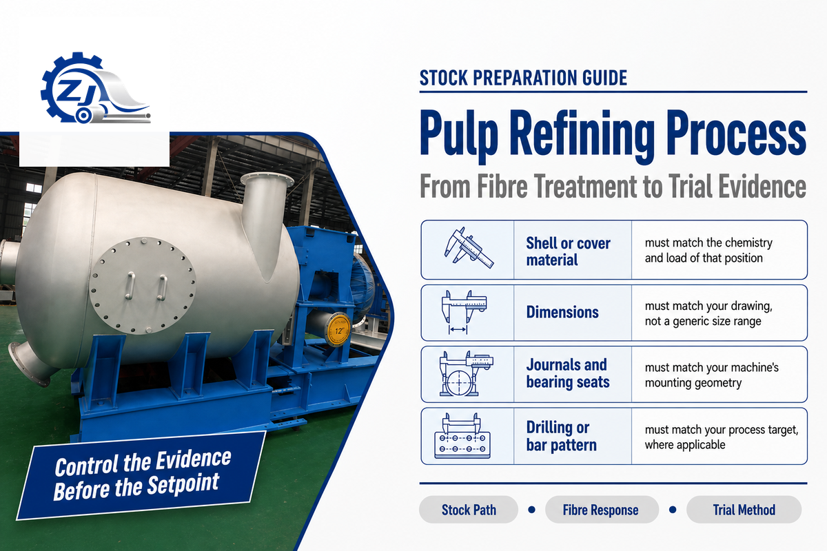
The pulp refining process is controlled mechanical treatment of prepared pulp fibres in stock preparation before sheet formation; a refiner changes fibre bonding and drainage response, not the pulping step itself. A small change made at the refiner affects factors like drainage, strength, bulk, formation, and machine behavior, but the positive result that we’re looking for may never become visible in the laboratory due to the traveling of the stock through chests and pipes. This means “lower the freeness” isn’t a safe operating limit. The process requires a defined fibre objective, a declared energy basis, time-synchronized samples, and grade-specific acceptance criteria.
This manual describes the path of stock through a disc refiner, explains what happens to the fibres, and converts the standard norms into a practical trial and troubleshooting methodology. The same lesson applies throughout the pulp and paper industry – no paper industry benchmark can set a single plate gap, consistency, and energy target for each mill. The characteristics of the furnish, equipment, test method, stock history, and the paper grade set the constraints.
The short version
Refining is controlled mechanical treatment, not simply power added to pulp. A useful result develops fibre bonding while keeping drainage, tear, bulk, fibre length, and runnability inside the mill’s agreed window. Read the energy dose, treatment intensity, fibre response, and final sheet together.
Pulp Refining at a Glance: Purpose and Position in Stock Preparation
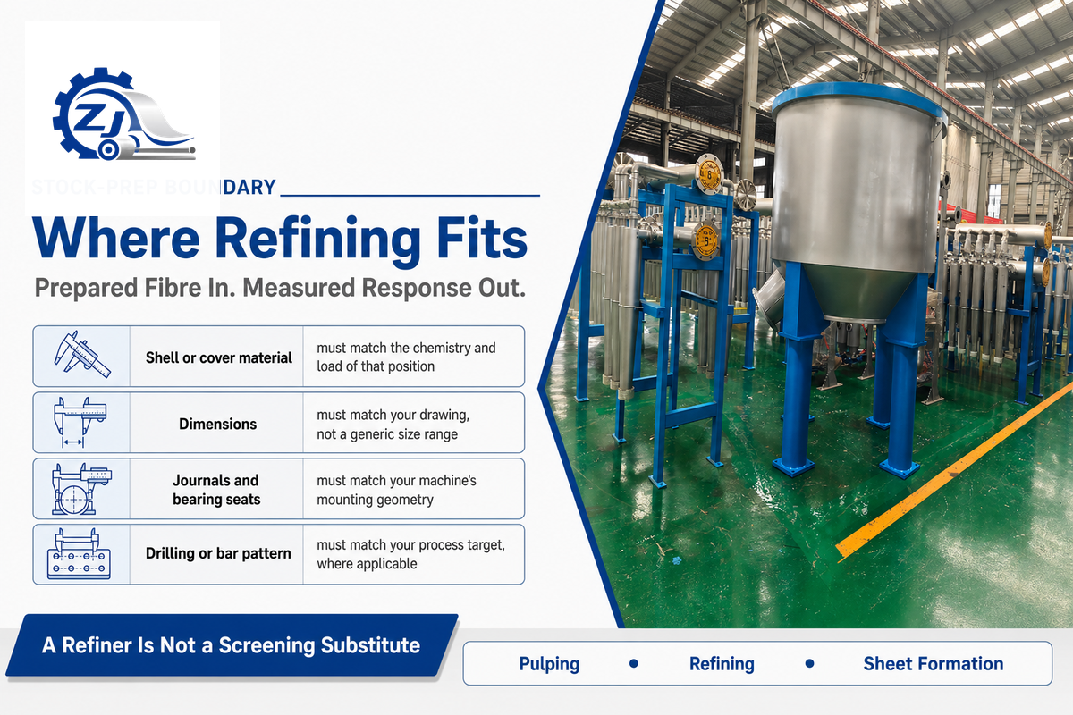
Pulp refining is the mechanical treatment of prepared fibres between pulping or repulping and sheet formation. This treatment affects the flexibility, surface condition, bonding potential, and drainage response of the fibres. It’s neither the chemical nor mechanical pulping step that frees the fibres, nor does it replace screening, cleaning, or deflaking. For the upstream equipment boundary, see Zejiang’s pulping equipment guide.
A typical route is pulper or pulp receiving → coarse contaminant removal → screening and cleaning → blending and consistency control → refining → machine chest and approach flow → headbox and sheet formation. Real routes differ. Some mills implement two stages of refining, reject treatment, recirculation, and/or separation of furnish streams. The dividing line between operations matters: a fibre bundle resulting from inadequate pulping, or contaminants escaping screening, will not become a refiner problem simply because it appears in subsequent stock-preparation stages.
| Operation | Primary job | Do not assume |
|---|---|---|
| Pulping or repulping | Liberate or redisperse fibres | That it creates the final bonding condition |
| Screening and cleaning | Separate contaminants and unsuitable particles | That a refiner can perform contaminant separation |
| Deflaking | Disperse incompletely separated fibre bundles | That its main purpose is deliberate fibre development |
| Refining | Develop fibre and sheet response for a grade | That more treatment always gives better paper |
The correct question isn’t whether the refiner is active. The correct question is whether the measured fibre change is the change this grade requires. That question defines accountability correctly. Stock preparation determines and controls the treatment condition, the laboratory verifies fibre and handsheet, and the paper machine determines if the drainage and the properties of the sheet remain workable.
Evidence boundary: Kerekes distinguishes specific refining energy from refining intensity as two descriptions of treatment. The 2016 paper describes a treatment-parameter framework, not a mill recipe; validate each target for the local furnish. Kerekes’ refining-parameter paper. The process and treatment boundaries defined in the refining description and differentiation of operation are of significance.
The 7-Step Pulp Refining Process Inside a Disc Refiner
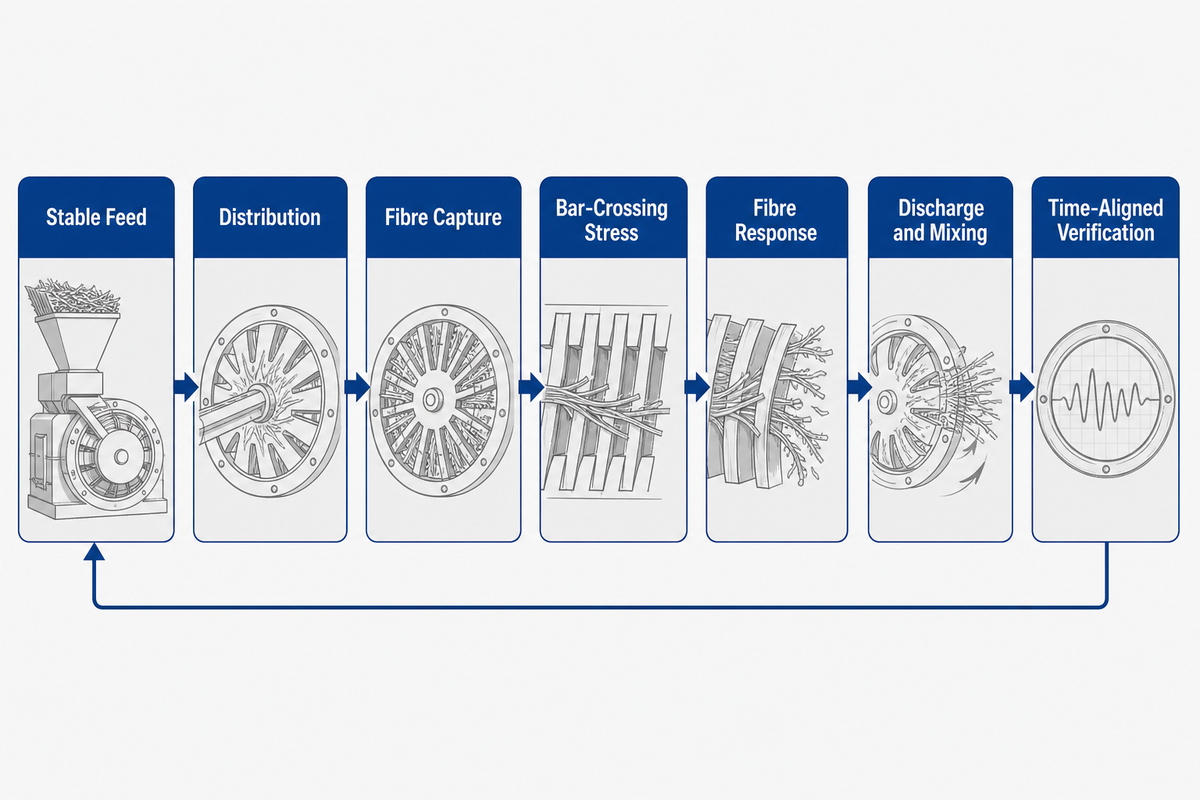
Inside a disc refiner, stock is stabilized, distributed into the refining zone, repeatedly exposed to rotor-stator bar crossings, and discharged for measurement and feedback. These seven stages make the stock path and feedback observable. They don’t refer to seven separate sections of the machine. Individual fibres don’t receive the same treatment.
- Condition the incoming stock. Confirm stock identity, blend ratio, and consistency. Check temperature and confirm pH where applicable. The flow must also be confirmed. A setpoint comparison is meaningless if the feed was changed at the same time.
- Feed and distribute the suspension. The stock is distributed to the active zone by the inlet and disc geometry. Hydraulic stability matters because uneven flow changes residence and motor response.
- Capture fibres near bar edges. Fibres travel in water through a narrow rotor–stator gap; some align and others pass with lighter treatment. Some cross edges, and some treatment is much lighter. The suspension is a changing population rather than a line of identical fibres.
- Apply repeated mechanical stresses. Bar crossings cause compressions, shearings, and elongations along with bending. The severity and the frequency of these are controlled by the plate, gap, load, and consistency of the network of fibres.
- Allow fibres to respond and rehydrate. Internal structure can become flexible; surfaces can become fibrillated and fibres can be shortened while generating fines. These processes can occur together, and may be beneficial or detrimental.
- Discharge and mix the treated stock. Refined pulp exits the active zone and enters downstream piping or a chest. This stock can mix with operating history for several minutes or many batches.
- Measure, align, and feedback. Link the correct process interval to the correct pulp and sheet samples. Compare energy, drainage, fibre morphology, strength, and sheet structure with the frozen baseline.
Process map
Stable feed → distribution → fibre capture → bar-crossing stress → fibre response → discharge and mixing → time-aligned verification
Use this map to connect PLC tags and sample timestamps to physical events. A conical refiner has different geometry, but the same discipline, defined input, treatment, discharge, and matched response, still applies.
Treating some parts of a fibre population much more than others can make population averages conceal lightly and heavily treated fractions. Bäckström and Mohlin provide an example of an estimate of industrial disc-refiner in which only 7–20% of fibres were treated in that context. The authors specify that this isn’t a universal treatment, but it does provide evidence to argue against imagining treatment is uniform.
Mechanism capsule: A 2026 peer-reviewed review describes capture and alignment, localized impact, multidirectional stress, then relaxation and rehydration. These four phases specify the mechanism in the context of the seven-step operation discussed previously; the additional steps incorporate feed, discharge, and feedback for a mill diagnosis. Review of the fibre-treatment mechanism.
What Refining Does to the Fibre, and What It Can Damage
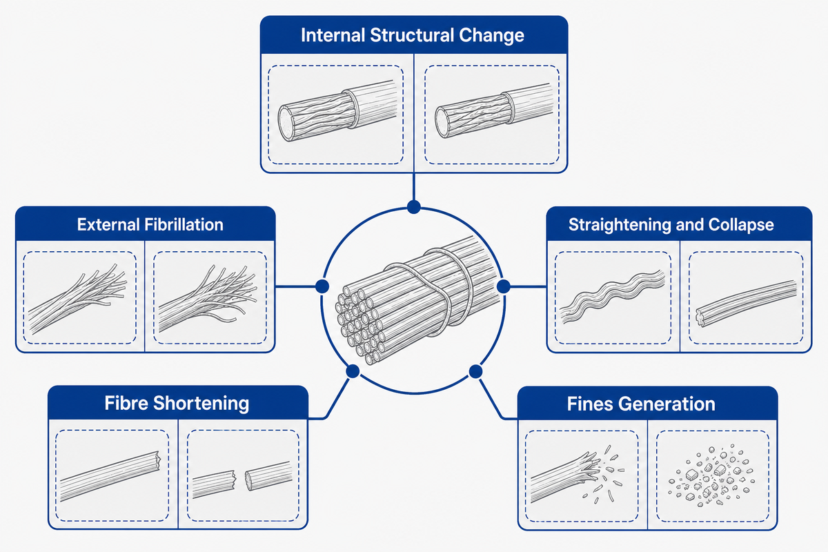
Refining may increase the flexibility and bondability of fibres; however, the same pass can also generate fines, shorten fibres, reduce bulk, or weaken the tear response. The ultimate goal isn’t the maximum degree of fibrillation. It’s about treating the least while achieving an agreeable response within the whole grade’s agreed drainage, strength, and sheet-structure window.
| Fibre response | Possible benefit | What to watch |
|---|---|---|
| Internal structural change | Greater flexibility and conformability | Drainage demand and reduced bulk |
| External fibrillation | More effective bonding area | Surface material and fines changing drainage |
| Straightening and collapse | Closer fibre contact and tensile development | Loss of porous sheet structure |
| Fibre shortening | May improve formation in a narrow context | Irreversible loss of long-fibre contribution and tear |
| Fines generation | Can contribute to bonding and surface closure | Slow drainage, retention sensitivity, and misleading freeness |
The table shows the directional relationship of terms, rather than showing absolute relationships. “More flexible” doesn’t specify how much energy to apply. Similarly, “lower freeness” doesn’t indicate the mechanism. From a constructive point of view, a useful mill trial integrates drainage methods with fibre-length or morphology data and handsheet properties. An improvement in tensile strength and a decrease in tear strength, bulk, or the long-fibre fraction outside of the grade limit, doesn’t constitute a pass because of the positive change in one factor.
The history of drying and recycling is important. Dried fibres can lose some capacity to reswell, a history often discussed as hornification. The use of recovered furnish also creates a response distribution problem since average measurements may conceal fractions that have very different responses. Record the drying history. Record prior drying and recycling history rather than describing the furnish only as “recycled.”
Measured boundary: A 2022 plate study used a mixed kraft furnish at 2–4% consistency, 1,500 rpm, and about 180 mL CSF. It measured fibre length, fines, water retention value, bulk, tensile, tear, and energy. Those conditions demonstrate a multi-property approach, not transferable setpoints. Measured plate-study results.
Low-Consistency vs High-Consistency Refining: Different Jobs, Not a Universal Winner
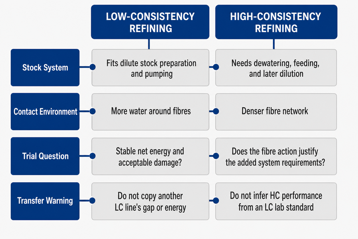
Low-consistency and high-consistency refining produce different fibre-contact environments and systems. Neither of them is the absolute best. Furnish, grade, the desired fibre action, dewatering and dilution capacity, installed drive, heat and the location of the stage determine which system is appropriate for a controlled trial.
| Decision point | Low-consistency route | High-consistency route |
|---|---|---|
| Stock system | Fits dilute stock preparation and pumping | Needs dewatering, feeding, and later dilution sized for the duty |
| Contact environment | More water around fibres; edge and flow variables remain important | Denser fibre network changes fibre–fibre interaction and heat |
| Trial question | Can the grade window be reached with stable net energy and acceptable damage? | Does the desired fibre action justify added feed, dewatering, power, and dilution requirements? |
| Transfer warning | Do not copy another LC line’s gap or energy | Do not infer HC performance from an LC laboratory standard |
Design relying solely on consistency labels is inadequate. The same nominal consistency can behave differently with a changed furnish, flow distribution, plate geometry, or temperature. The BioResources loop study reports that the changing consistency of a sample resulted in changes to fibre shortening, bulk, tensile, and even water retention under nominally controlled intensity or energy factors. This indicates effects within the studied bleached kraft softwood and test configuration; those factors and ranges remain outside a universal mill operating recipe. For this reason, consistency must be recorded instead of being disregarded as background information.
ISO/TS 11371:2023 has given some instructions and thoughts on laboratory simulation of industrial low-consistency refining for 3-5% stock concentration. This is a useful vocabulary and comparison boundary. It should not be regarded as the boundary of high-consistency operation in the design of plants.
Scope capsule: ISO/TS 11371:2023 has explicitly defined a 3-5% range of low-consistency laboratory simulation. Use these two limits to define the standards scope, not to aim at a mill setting. ISO laboratory-refining guidance. A high-consistency proposition has to be backed by a complete furnish trial, material balance, heat analysis, and a utility study.
Control Variables That Change the Refining Result
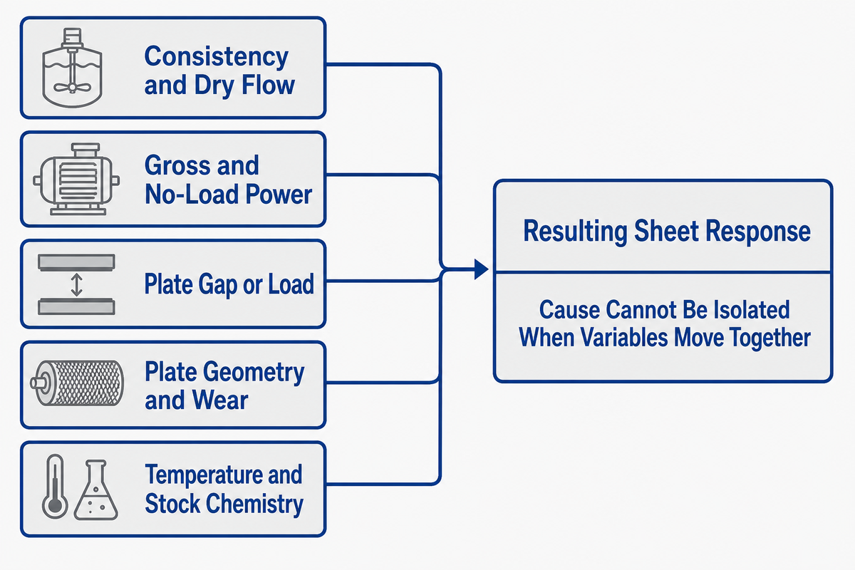
Consistency, flow, power, plate design and wear, gap and load, speed, temperature, and furnish interact. If two of these change at a given time then the resulting sheet won’t show which of them caused the change.
“Specific refining energy and refining intensity are the two most commonly used parameters.”
| Variable | What to record | Common confounder |
|---|---|---|
| Consistency and dry flow | Sampling method, oven-dry basis, flow timestamp | Using wet flow as dry mass flow |
| Gross and no-load power | Meter source, stable hydraulic state, definition | Comparing suppliers with different no-load methods |
| Plate gap or load | Control mode, calibration, vibration, actuator position | Assuming displayed gap equals effective treatment everywhere |
| Plate geometry and wear | Pattern, bar and groove data, diameter, direction, hours and inspection | Calling different patterns equivalent because they fit |
| Temperature and stock chemistry | Inlet and outlet values, pH or additives when relevant | Attributing a viscosity or swelling change only to the plates |
How to Calculate Net Specific Refining Energy
On an oven-dry declared basis, a working form is:
Net specific refining energy = (gross operating power − declared no-load power) ÷ oven-dry pulp flow
Hypothetical example only: if gross power is 520 kW, the agreed no-load value is 170 kW, and oven-dry flow is 7.0 t/h, the net value is (520 − 170) ÷ 7.0 = 50 kWh/odt. That result becomes comparable only when both trials use the same meter boundary, no-load definition, dry-flow method, and steady-state rule.
Specific (or Unit) Energy is the energy per unit of dry mass. The specific edge load describes a different aspect of energy application. Specific edge load depends on the length of a plate bar edge, bar edge speed, and net power. Equal energy at different intensities can lead to different fibre responses; equal intensity at different consistencies or furnishes can also lead to different responses. Don’t substitute one for the other.
Loss-basis capsule: A 2020 review places reported no-load power at roughly 20–50% of gross power in reviewed LC contexts, with measurement definitions differing by as much as 35%. These are literature ranges, not acceptance limits. Declare the method before comparing 1 kWh/odt result with another.
The Refining Response Triangle: Drainage, Strength, and Sheet Structure
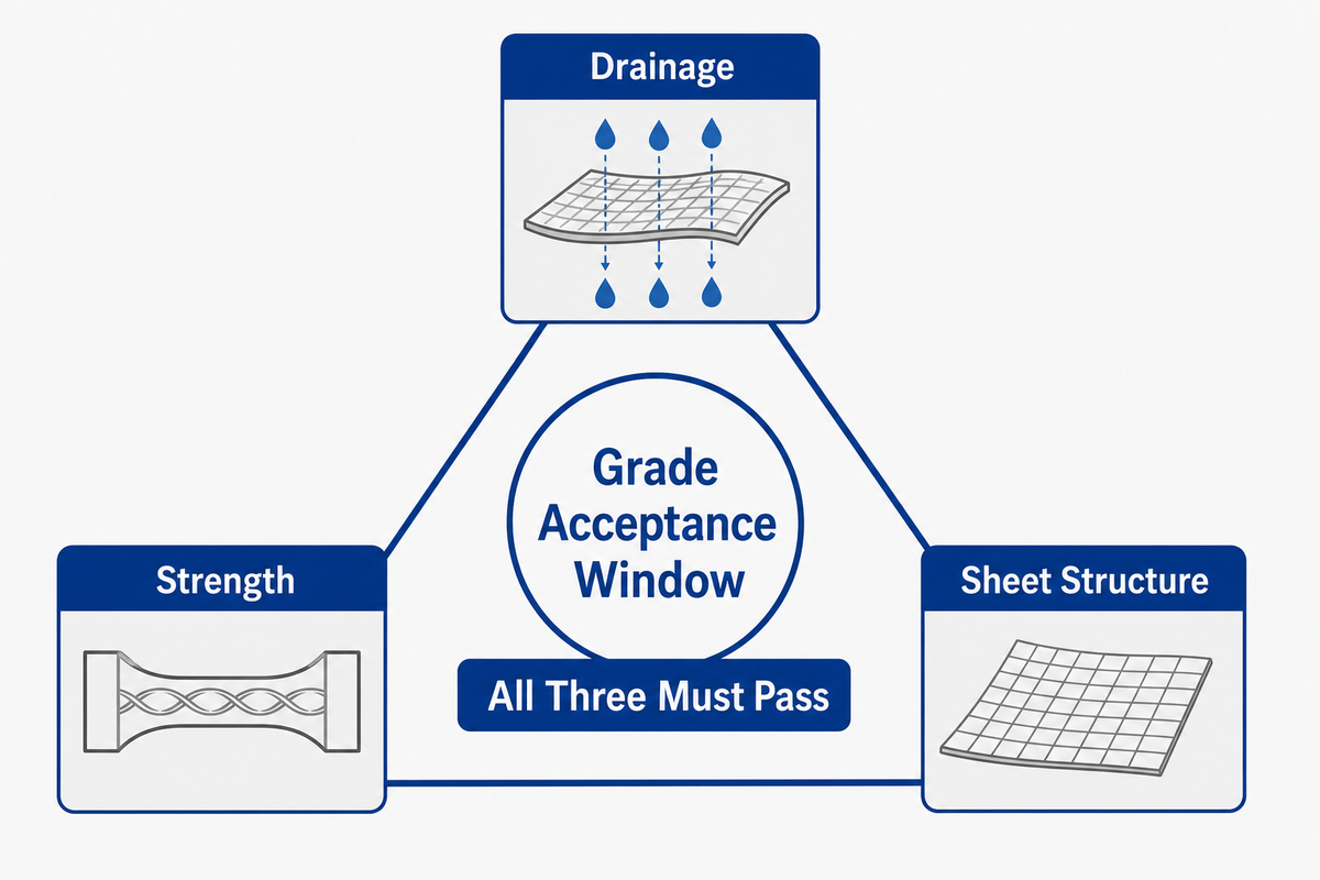
A setting passes only when drainage, strength, and sheet structure all remain inside the agreed window. This Refining Response Triangle prevents a freeness change from replacing paper quality. It’s a decision rule not hard limits; each mill prescribes its baseline, methods, and constraints.
STRENGTH
tensile • tear • bond
tensile • tear • bond
DRAINAGE
CSF or °SR • machine drainage
CSF or °SR • machine drainage
SHEET STRUCTURE
bulk • formation • fibre integrity
bulk • formation • fibre integrity
| Triangle side | Evidence | Failure that one number misses |
|---|---|---|
| Drainage | One declared CSF or Schopper–Riegler method plus machine observation | A drainage result cannot identify fibrillation versus cutting |
| Strength | Grade-relevant tensile, tear, internal bond, or other agreed tests | Tensile gain can coexist with unacceptable tear loss |
| Sheet structure | Bulk, formation, porosity where needed, fibre length and fines | Bonding gain can hide density or fibre-integrity damage |
Canadian Standard Freeness and Schopper–Riegler are methods of assessing drainability as opposed to indicators of quality. Record the exact method and edition, stock preparation, temperature, and water conditions. ISO 5267-2:2025 reports CSF in millilitres and warns that a fines-rich treatment can produce anomalous “false freeness” behaviour below 100 mL. That number is a method warning, not a recommended target.
TAPPI T 227 om-26 describes a dilute test using 3 g of pulp in 1 L of water and notes that applicability to all pulp types remains undetermined. ISO 5267-1:1999 covers the Schopper, Riegler method and was confirmed current in 2021. A report that states “freeness improved” does not specify the method and is therefore insufficient for comparison.
The triangle helps avoid a purchase mistake. Though two plate trials may reach the same tensile result, they may have distinct tear characteristics, bulk, fines, or long-fibre retention. Procurement should approve a plate or refiner duty only after the trial window has captured those characteristics that ensure the grade remains saleable and the machine operational.
Method capsule: TAPPI T 227 om-26 uses 3 g pulp in 1 L water. ISO 5267-2:2025 reports CSF in mL and flags false-freeness risk below 100 mL for some fines-rich treatments. Keep those numeric conditions attached to the test, never the mill target. ISO Canadian Standard freeness method.
Why Furnish and Grade Change the Refining Recipe
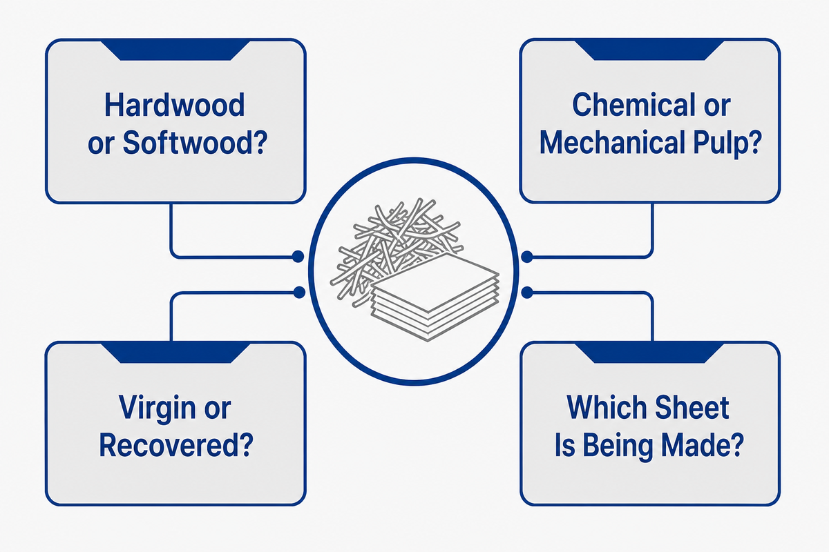
Furnish identity and paper-grade objectives determine what describes necessary refining. Hardwood, softwood, mechanical and chemical pulp, and recovered fibres have different characteristics concerning stiffness, geometry, surface quality, and history of treatment. A transferred setpoint can reproduce an energy number yet miss the intended fibre response when furnish details are absent.
| Furnish question | Why it changes the trial | Record before testing |
|---|---|---|
| Hardwood or softwood? | Fibre length and morphology shift formation, strength, and cutting risk | Species or supplier grade, blend percentage, incoming morphology |
| Chemical or mechanical pulp? | Fibre structure and surface differ; rejects can have a separate duty | Pulp route, yield class, brightness and strength purpose |
| Virgin or recovered? | Prior drying and recycling may reduce reswelling and add mixed history | Recovered grade, previous use, contamination and refining history if known |
| Which sheet is being made? | Tissue, packaging, printing, and specialty papers value different tradeoffs | Basis weight, strength set, bulk, formation and drainage constraints |
Blend changes should be treated similar to trial changes even when the refiner setpoints are unchanging. The same should apply to broke rate, ash, wet-end additives, and temperature where applicable. Stabilize the furnish lot for a sufficient length of time to yield a significant result or model explicitly the change to avoid it being one of many unimportant changes.
“Gentle refining” also demands a definition. It may mean lower intensity, staged energy, less fibre cutting, or a smaller change per pass; define the intended outcome. Record desired result and its indicator, or two teams may both employ gentle treatment using different energy bases and measuring different paper properties.
Furnish capsule: In the bounded Olejnik study, a 130 dm³ loop ran below 35°C on bleached kraft softwood pulp. Changes in consistency affected water retention, fibre shortening, tensile and bulk at approximately constant energy or intensity. The equipment volume and temperature are study variables; they aren’t limitations of the plant. Bounded consistency-loop study.
Troubleshooting Refining Drift with the Setpoint-to-Sheet Causality Chain
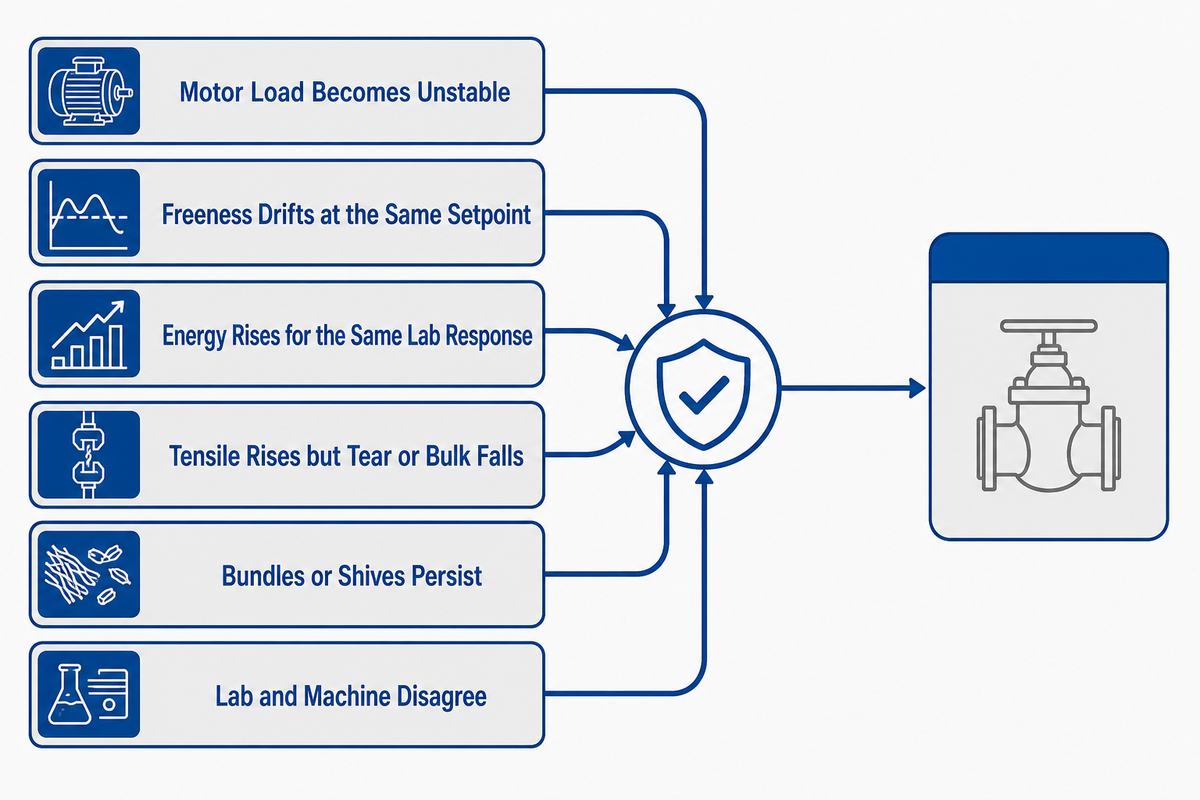
Check furnish, sampling, hydraulics, instruments, and controls before changing plate gap; inspect plates after excluding these causes. The baseline is protected by this sequence. It doesn’t imply plates are always the last cause; it prevents a mechanical change from concealing a feed, timing, or measurement problem.
Furnish → Feed and hydraulics → Instrument truth → Refiner setpoint → Mixed inventory → Correct sample → Sheet response
| Symptom | Confirm first | Then isolate |
|---|---|---|
| Motor load becomes unstable | Flow, consistency, inlet pressure, valve state, meter quality | Control loop, actuator, vibration, plugging, plate condition |
| Freeness drifts at the same setpoint | Furnish lot, blend, temperature, sampling point and test method | Net energy basis, gap/load calibration, wear |
| Energy rises for the same lab response | Dry flow and no-load definition | Hydraulic losses, plate wear, changed furnish response |
| Tensile rises but tear or bulk falls | Matched sample and test conditioning | Fibre shortening, fines, intensity and plate pattern |
| Bundles or shives persist | Repulping, deflaking, screening and reject path | Only then assess a refining-stage duty |
| Lab and machine disagree | Residence time, chest mixing, clock alignment and sample identity | Wet-end changes and laboratory repeatability |
In one full-scale CTMP study, residence in the refiner was about 1 second, while a measured path after the latency chest involved about 90–120 minutes of settling. These values are specific to that RGP82CD line and that sampling arrangement. These data show the delay must be measured for your system; copying the study’s timing cannot determine local residence.
If a sample combines stocks made before and after a setpoint change, the laboratory result is a mixed-history sample. Mark the change time, estimate each vessel and pipe delay, wait for an agreed turnover condition, and hold the baseline until the first clearly attributable sample arrives. A fast PLC response doesn’t eliminate physical inventory.
Time-alignment capsule: The 2023 full-scale CTMP study sampled 6-second process data, reported about 1 second in the refiner, and found 90–120 minutes of settling after the latency chest. The authors judged the downstream sample point unsuitable for direct control of an immediate refiner change. Full-scale timing study.
Run a Mill Trial Without Losing the Baseline
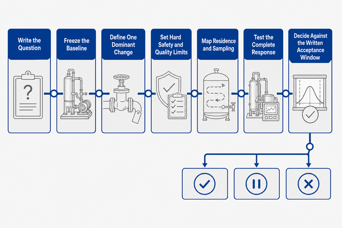
A defensible mill trial freezes the baseline, changes one dominant variable, waits for attributable stock, and applies predefined accept, hold, and rollback rules. The trial isn’t a demonstration of a supplier claim. It’s a controlled comparison under the mill’s furnish, equipment, laboratory, and grade conditions.
- Write the question. Name the property tradeoff being tested, such as maintaining tensile while reducing energy without losing tear or bulk.
- Freeze the baseline. Record furnish, blend, consistency, flow, temperature, gross and no-load power, plate identity, control mode, drainage method, fibre data, and sheet tests.
- Define one dominant change. A new plate pattern, gap/load adjustment, energy step, consistency change, and furnish change must not enter as one unexplained bundle.
- Set hard safety and quality limits. Include vibration, motor, hydraulic, drainage, broke, and critical grade constraints. Operating procedures and equipment limits always take priority over this guide.
- Map residence and sampling. Synchronize clocks, label samples, and wait for the agreed stock turnover. Keep pre-change and transition samples separate.
- Test the complete response. Use the Refining Response Triangle along with energy, fibre morphology, and runnability data. Repeat the test enough times to distinguish stable shift from test variation.
- Decide against the written acceptance window. Accept, hold for further evidence, or roll back. Don’t alter the target after observing an attractive isolated result.
All methods should be exchanged before the trial, not after a disagreement. Include pulp preparation, conditioning, test edition, units, number of replicates, and treatment of outliers. Keep raw observations for each sample with the summary so that a later plate or control comparison is done with the same measure.
Here, no plant results are shown as a case study. The examples are given to show the calculation and evidence handling. A site acceptance plan must be reviewed and signed by the mill’s responsible process, electrical, mechanical, safety, and quality personnel.
Comparison capsule: In an open access 2020 study, treatment paths were able to achieve similar trends in tensile response. However, the bulk, tear and retained long-fibre fraction presented divergent results. A trial requires at least 3 outcome families, drainage, strength, and sheet structure, before it can be considered. Comparative fibre-response study.
The study’s energy map ranged from 0–493 kWh/t for baseline LC treatment, with microfibre preparation reported at 1,567 kWh/t, 2,242 kWh/t, and 2,430 kWh/t. Composite targets covered 113–493 kWh/t; measured fibre lengths covered 0.200–10.000 mm. A separate plate study above used 2–4% stock. Those values describe experiments and aren’t recommended production doses.
When Refiner Plates and Screening Hardware Enter the Diagnosis

If a persistent change is observed in the normalized process evidence, hardware should be inspected. Change in furnish, sampling, or hydraulics may not explain the change. Plate wear, damage, plugging, pattern, direction, or fit may explain a persistent response shift after process causes are checked. Screening hardware will be part of the review if contaminant, fractionation, or reject behavior is noted outside of refiner.
Prior to submitting a request for replacement parts, document the identifier of the plate maker, pattern or drawing, refiner model, key dimensions, metallurgy, and operating hours. Take photographs and document the operating condition. Add process symptoms and a time trend. “Same size” isn’t sufficient; bar geometry and open area can change flow and energy behavior, even if the same plate is used.
| Evidence | Route | Required handoff |
|---|---|---|
| Stable feed but persistent load/response shift | Inspect plates, gap mechanism and refiner internals | Trend, baseline, inspection, plate identity |
| Reject, debris or fractionation problem | Review screens, baskets and upstream separation | Contaminant, slot or hole data, flow and reject balance |
| Changed furnish or target grade | Return to process trial before ordering by old duty | New furnish brief and target window |
For dimensions, materials, fit, and ownership of the quotation, refer to Zejiang’s refiner plates and screen baskets for further information. That’s the commercial handoff, and this guide will remain the process, measurement, and diagnostic owner.
Plate-study capsule: A single-disc study for 2022 analyzed lengths of plate bar edges at 55 and 97 km/s at 1,500 rpm. It demonstrates the importance of keeping a record of a trial. These two edge lengths indicate the test plates. The two edge-length values describe those test plates; they do not predict a different refiner’s result. Plate experiment and measured response.
Integration, Utilities, and the RFQ Handoff

A productive RFQ integrates the process basis of the trial into mechanical, electrical, piping, control, installation, and acceptance scope. Offer furnish, consistency, dry flow, installed power, present hardware, required properties, sample methods, and acceptance range. Missing interfaces will result in comparable looking quotes for different systems. The company background establishes Zejiang’s identity; use the parts hub for product specifications and keep the mill’s trial acceptance separate.
Include the existing equipment arrangement and proposed change rather than an undefined system. For a retrofit, detail the foundations, footprint, lifting, piping interconnections, location of valves and instruments, voltage and frequency of the motor, type and placement of starters/drives, PLC/DCS signals, guarding, lubrication, and sealing water, drainage, shutdown window, and responsibility for commissioning. For wear parts, link each dimension and drawing revision to the specified refiner position. For model and sizing scope, see Zejiang’s disc refiner page; the mill trial in this guide remains the acceptance basis.
Place a unit alongside every number; plate and pipe dimensions in mm, flow of stock in m³/h and oven dry t/h, consistency in %, temperature in °C, rotation speed of shaft in rpm, load of motor in kW, operating frequency in Hz, and normalization treatment in kWh/odt. A naked number can’t indicate an interface or pass a test.
Evidence-first refiner RFQ checklist
| Field category | Project value | Why it matters | Acceptance evidence |
|---|---|---|---|
| Furnish and grade | Pulp types, blend, prior drying/recycling, basis weight | Defines fibre response and tradeoffs | Approved furnish brief and baseline |
| Capacity basis | Consistency, wet flow, oven-dry t/h, range | Sets hydraulic and energy calculation basis | Calibrated instruments and mass balance |
| Existing refiner and plates | Model, position, diameter, direction, pattern, material, drawings | Prevents fit and duty mismatch | Inspection, photos and signed drawing |
| Power and controls | Motor data, no-load method, drive/starter, PLC tags and interlocks | Defines energy, start-up and interface scope | I/O list, motor documents and witnessed checks |
| Utilities and layout | Water, lubrication, piping, drains, footprint, access and lifting | Exposes installation exclusions | Interface matrix and site drawing |
| Temperature and chemistry | Inlet/outlet °C, pH, relevant additives and water source | Separates fibre response from stock-condition change | Calibrated readings and sample record |
| Instrumentation basis | Tag list, units, ranges, calibration status and clock source | Makes time-aligned evidence auditable | Calibration and timestamp check |
| Performance window | Drainage method, strength, bulk/formation, fibre integrity, energy basis | Stops one attractive number from deciding acceptance | Agreed trial plan and matched results |
| Delivery and responsibility | Shutdown, installation, training, spares, commissioning and warranty boundaries | Makes bids commercially comparable | Responsibility matrix and signed protocol |
The acceptance criteria should spell out what happens if a limit is exceeded (stop, hold, inspect, roll back). It should also identify who has responsibility for sample collection, lab tests, control changes, mechanical inspection, and final sign-off. This clarifies the RFQ on the parts list and establishes an operating contract.
Handoff capsule: A process value will be comparable only if its unit and basis travel with it: kW for power, oven-dry t/h for pulp flow, kWh/odt for net specific energy, and mL or °SR with the named drainage method. Four labels can prevent a technically false comparison. Declared CSF measurement method.
Measured Evidence Ledger: Numbers and Their Boundaries
| Source class | Reported conditions | Safe use |
|---|---|---|
| LC laboratory guidance | 3–5% stock | ISO/TS 11371 scope only |
| Consistency study | 2–8% discussion; below 35°C | Bleached kraft softwood test context |
| Plate experiment | 2–4% stock; 1,500 rpm | Compare measured responses, not plant setpoints |
| No-load review | 20–50% of gross; methods up to 35% apart | Require a declared loss basis |
| Full-scale timing study | 6 sec data; about 1 sec residence; 90–120 min settling | Proof that each mill must map delay |
| Microfibre comparison | 0–493 kWh/t baseline; 1,567–2,430 kWh/t preparation; 0.200–10.000 mm measurement range | Experimental comparison only |
Frequently Asked Questions
Why is pulp refined before the paper machine?
Pulping or repulping prepares fibres; refining adjusts how they flex, bond, and drain for the sheet. It’s placed before approach flow and formation so the mill can produce the furnish and then verify its machine behaviour. Low freeness alone isn’t acceptable.
How does refining affect paper quality?
Proper treatment can improve fibre flexibility, contact, and bonding area. Excess or poorly matched treatment can create fines, shorten fibres, slow drainage, reduce bulk, or weaken tear. Evaluate the response as a system of properties rather than a single laboratory test outcome. The Refining Response Triangle above summarizes drainage, strength, and sheet structure.
What is the difference between high- and low-consistency refining?
The regimes subject the fibres to varying modes of suspension and contact, and require different feed, dewatering, dilution, power and heat systems. Neither solution can address all requirements. Low-consistency laboratory references can’t support high-consistency performance. Compare the options against the actual furnish and utility limits.
Does lower freeness always mean better paper?
No. Freeness describes drainage under the declared test method. A lower result may reflect bond development or more cutting and fines. It may also be a result of slow machine drainage, low bulk and weak tear. Answer the other two sides of the response triangle.
What is the difference between refining and deflaking?
Deflaking disperses incompletely separated fibre bundles, with limited fibre development. Refining performs repeated mechanical treatments to alter the flexibility and bond strength of the fibre. In reject systems, equipment effects can overlap; compare the starting material, operating goal, and observed fibre response rather than relying on the equipment label.
When should refiner plates be inspected?
Don’t employ a universal operating-hour count. Inspect when normal operating baselines indicate shifts in power, motor stability, drainage, strength, vibration, or hydraulic behavior; first eliminate furnish, sampling, timing, and instrument shifts. Analyze this evidence in conjunction with a safe shut down and manufacturer’s specifications. If a worn screen or basket could account for the same symptoms, capture the behavior of rejected and contaminant materials. Don’t order a replacement on the basis of a symptom.
Turn the Process Evidence into a Clear Parts or Equipment Brief

Bring the furnish, dry flow, present hardware, utilities, and three-part acceptance window together before asking for a quote. Zejiang can review the supplied operating and dimensional information against the requested scope; final operating limits remain subject to the mill’s own safety and process approval. Example of measured plate-trial evidence.
References & Sources
- Kerekes, R. J., Characterizing Refining Action in PFI Mills, Paper and Biomaterials, 2016.
- Olejnik, Impact of Pulp Consistency on Refining under Constant SEL and SEC, BioResources, 2013.
- ISO 5267-1:1999, Schopper, Riegler method, confirmed 2021.
- ISO 5267-2:2025, Canadian Standard freeness method.
- TAPPI/ANSI T 227 om-26, Freeness of pulp.
- ISO/TS 11371:2023, Guidelines for laboratory refining of pulp.
- Liu et al., No-Load Power and Specific Energy in Low-Consistency Refining, Journal of Korea TAPPI, 2020.
- Ryu et al., Low-Consistency Refiner Plate Design and Pulp Properties, Applied Sciences, 2022.
- Jahangir and Olson, Treatment Paths, Strength, Bulk, and Fibre Length, Cellulose, 2020.
- Fairbank, The Future of Low-Consistency Refining, Pulp & Paper Canada, 2023.
- Kim, Review of the Refining Mechanism, Journal of Korea TAPPI, 2026.
- Bäckström and Mohlin, Influence of Refining Heterogeneity on Paper Properties, BioResources, 2019.
- Karlström, Hill, and Johansson, Data-Driven Soft Sensors in Refining Processes, BioResources, 2023.
This article uses independent standards and published research for technical claims. Zejiang’s own page is cited only for its product scope and navigation. The guide contains no claimed customer result or universal performance guarantee. Company identity was checked against the public About Us page.




![Refiner Plates & Screen Baskets [Complete Guide]](https://zjpapermachine.com/wp-content/uploads/2026/07/refiner-plates-screen-baskets-guide-featured-150x150.png)
![Doctor Blade: Types, Materials & How It Works [Guide]](https://zjpapermachine.com/wp-content/uploads/2026/07/doctor-blade-guide-featured-1-150x150.png)
![Pulping Equipment: How Paper Pulping Works [Guide]](https://zjpapermachine.com/wp-content/uploads/2026/07/pulping-equipment-guide-featured-150x150.png)