
Get in touch with Zejiang Paper Machinery Company


Updated: September 2026 · Reviewed by: the Zejiang Paper Machinery technical team
Press, Vacuum & Couch Rolls are best recognized by three characteristics: the location of the roll, the kind of force it exerts, and the location of the removed water. There’s meaningful overlap across the three labels. At the couch position, vacuum may assist the roll, while a suction press roll combines an internal vacuum zone with mechanical nip action. Treating the three names as individual catalog boxes results in ineffective troubleshooting and unsatisfactory purchasing activities.
Quick answer
Map the installed position and sheet path first. Then time-align solids, vacuum and airflow, nip conditions, clothing state, vibration and recent changes. No single symptom or gauge value can prove a roll fault. Hands-on inspection belongs inside the mill’s authorized hazardous-energy procedure; machine-specific design and quote work belongs on the linked commercial page.
This technical guide is intended for the production, process, maintenance and purchasing teams who require a shared factual basis. It covers definitions, mechanisms, measurement, diagnosis, safe inspection, and escalation. It won’t repeat the models, materials, dimensions, drawings, drilling patterns, pricing, lead time or RFQ content covered by Zejiang’s commercial roll page.
What Are Press, Vacuum & Couch Rolls?

A press roll functions in a nip that compresses the wet web and typically directs expressed water to a press felt. A vacuum roll describes a broader construction or operating definition. It’s a perforated rotating shell that operates over one or more stationary internal suction zones. A couch roll refers to a forming-section position that’s adjacent to the point at which the sheet leaves the forming fabric. These definitions may apply to a single roll.
In opting for practicality, the naming rule is to never let the noun carry the full meaning. “vacuum roll” doesn’t allow a technician to determine whether the roll is in the couch, pickup or press position. “press roll” reveals nothing about whether the roll is plain, grooved, blind-drilled or suction-assisted. “couch roll” is more descriptive, but still requires the drawing to fully describe the suction zone, shell, seals, bearings and water route.
| Identification axis | Question to answer | Examples |
|---|---|---|
| Installed position | Where does the sheet meet the roll? | Couch, pickup, first press, second press |
| Applied force | Vacuum, nip compression, support or transfer? | Suction zone, loaded nip, supporting wrap |
| Water path | Where should water and air move? | Through fabric, into felt, through shell holes, to separator |
Each shift log, vibration route, and outage finding, as well as refined requests for roll specifications, should use all three coordinates. Employing this approach discourages different departments from providing different kinds of evidence to the same generic name.
Evidence note: An NC State papermaking reference describes a couch roll that removes water by applied vacuum. That single example establishes the overlap: couch identifies a position, while vacuum describes the water-removal method. It does not define every installed couch-roll design.
Where Does Each Roll Work in the Wet End?
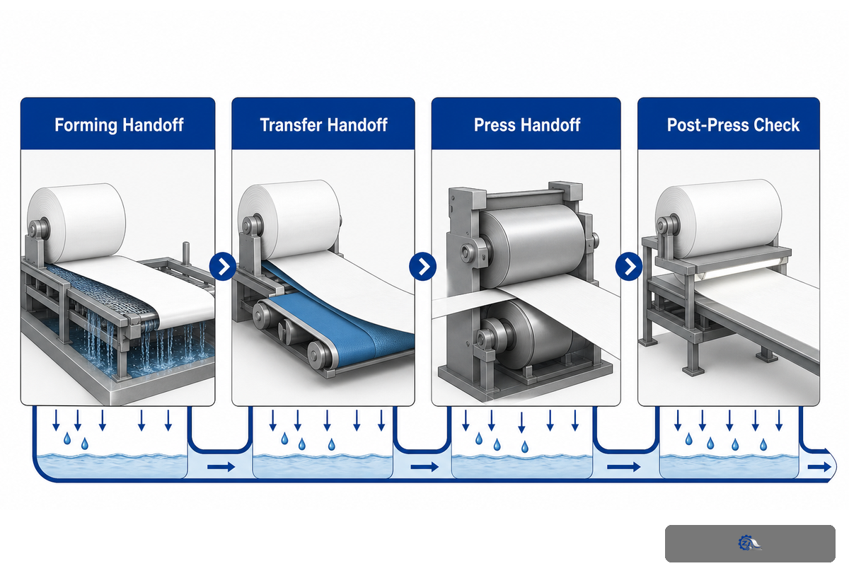
The wet end is a series of water removal and sheet transfer conveyance, as opposed to a collection of rolls in isolation. At the end of forming, the sheet could pass over a suction couch roll prior to pickup and one or more press nips. The exact order varies with machine design, so a useful map should focus on functions and handoffs as opposed to assuming each line is a conventional Fourdrinier.
Those arrangements are not universal: twin-wire, gap-former and tissue machines position their vacuum-assisted elements, pickup points and presses differently. Begin with the latest machine drawing. On that drawing, trace both clothing paths and web direction before marking each active suction zone, mating nip and sample point. Indicate each sampling position on the current machine drawing. Solids values after the couch and after a press nip answer different questions.
Wet-End Roll Function & Evidence Map
- Forming handoff: record sheet solids at a named point, fabric condition, vacuum zone, airflow if available and water removal.
- Transfer handoff: record sheet support, pickup stability, felt contact, draw and the exact location of instability or breaks.
- Press handoff: record inlet/outlet solids, nip/load context, felt state, vacuum zone where present and rewetting risk.
- Post-press check: connect the roll evidence to moisture profile, runnability, quality and the next process constraint.
Evidence of downstream dryness shouldn’t be attributed to a single roll change if an intermediate felt, nip, vacuum zone or sample boundary also changed. The map should also illustrate evidence pertaining to each handoff and what was different in the comparison run.
Evidence note: The 2020 BioResources review covers the path from the headbox jet through the final wet-press nip. It treats formation, vacuum dewatering and pressing as connected unit operations, which supports position-specific sampling rather than one undifferentiated “wet-end dryness” number.
How Do Vacuum and Nip Dewatering Work Together?
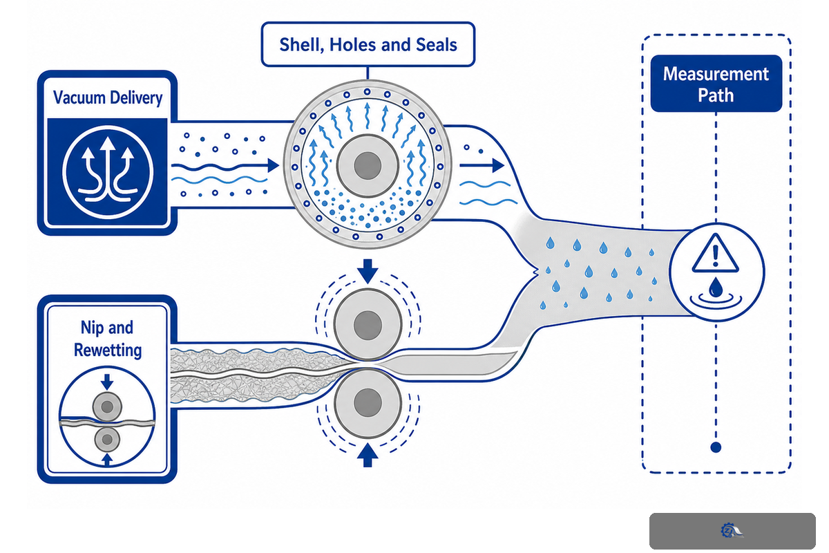
The wet web carries the outcome of both stages, even though vacuum drainage and press-nip drainage work through different pressure regimes. A vacuum-induced pressure difference draws air and water through the sheet together with its supporting clothing. During the short dwell, a press nip compresses the web and felt and displaces water under mechanical load. The next section of the path can carry the water or bring some of it back by rewetting.
Therefore, an indicated vacuum reading isn’t a result in itself. In addition to air capacity, dewatering depends on leaks, seal contact, open shell holes, suction-zone geometry, fabric or felt condition, furnish, basis weight, speed, dwell, water removal, where and how solids are measured, and adjacent sections of the path; more water removal at one location is not a win if formation, runnability or a later dewatering stage becomes worse. Higher gauge readings can coexist with restricted flow or a downstream blockage.
| Hidden bottleneck | Evidence to collect | Why vacuum alone can mislead |
|---|---|---|
| Furnish and sheet structure | Grade, basis weight, fines/filler and chemistry state | Resistance through the web can change |
| Fabric or felt | Condition, age, contamination, permeability method | Clothing may limit acceptance or discharge |
| Vacuum delivery | Vacuum and airflow at defined points, pump/load trend | The same pressure can occur with different flow |
| Shell, holes and seals | Restriction map, leakage evidence, seal condition | Losses can sit between gauge and sheet |
| Nip and rewetting | Load context, dwell, felt water handling, outlet solids | Water removed in one zone may return later |
| Measurement path | Instrument, status, location, method and timestamp | A changed method can imitate process change |
Publications may report precise pressure and solid values without providing a mill setpoint. One study discussed in the academic review used pressure differences up to 70 kPa and reported different results for LWC paper and SC fibers. The reported pressure is not a setpoint; furnish, test boundary and measured response must accompany every number.
Assess each change against solids at the stated position, airflow, vacuum, clothing condition, sheet transfer, moisture profile, breaks, drive load and finished quality. A water-removal gain at one location is not a better result when formation, runnability or the next dewatering stage performs worse.
Evidence note: In the academic review, a cited filtration study reached pressure differences up to 70 kPa, yet grade-specific solids responses differed. Paper360 also notes machine speeds from 200 to 1,100 m/min in one field discussion. Both figures show boundary sensitivity, not recommended settings.
Press Roll vs Vacuum Roll vs Couch Roll: What Changes?
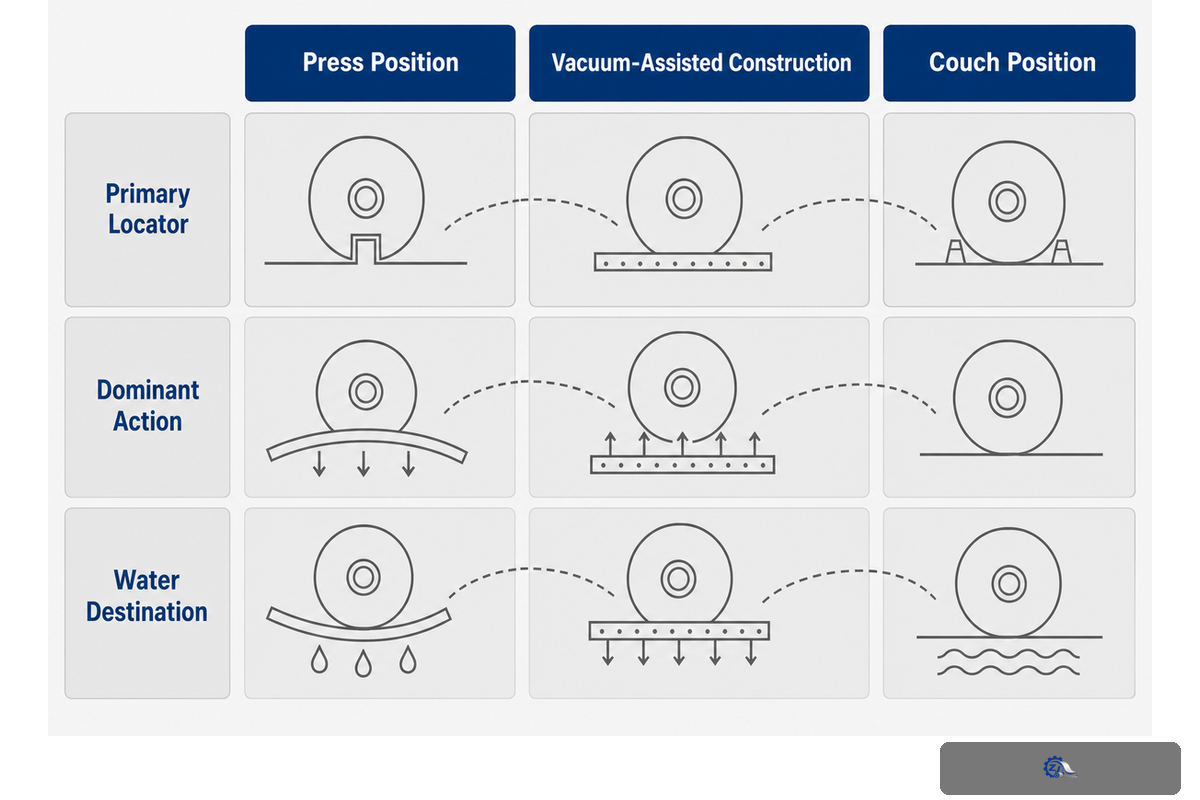
The best comparison is multi-axis. Position indicates which handoff or sheet transfer the roll serves. Applied force indicates whether suction, nip compression or support dominates. The water path indicates which cloth, holes, channels, separators and removal equipment fall in the diagnostic boundary. Those functional fields outlast whatever product name a seller chooses.
| Comparison field | Press position | Vacuum-assisted construction | Couch position |
|---|---|---|---|
| Primary locator | Loaded press nip | Internal suction zone | End of forming section |
| Dominant action | Mechanical compression | Pressure difference and flow | Final forming drainage and transfer support |
| Supporting clothing | Usually press felt | Fabric or felt, depending on position | Forming fabric |
| Water destination | Felt and press dewatering path | Through shell to suction system | Through fabric/shell to couch vacuum path |
| Typical evidence | Inlet/outlet solids, load context, felt and profile | Vacuum/airflow, seal, holes, zone and discharge | Couch solids, sheet transfer and fabric contact |
| Overlap | Can be a suction press roll | Can be couch, pickup or press | Often vacuum-assisted |
Dimensions, materials, cover selection, shell drilling and allowable loads are intentionally omitted. They’re part of the customer’s drawing, OEM documentation and machine-specific commercial assessment. This guide only provides the evidence framework preceding this assessment.
paper making teams may hear overlapping search terms. A vacuum couch roll or paper machine couch roll narrows the position; a vacuum press roll or press suction description points to the press section. Words such as roller, cylinder, cylinder mould, stainless steel, Cast Iron, Rubber Roll, Face Length and hardness describe equipment or specification fields; search records may also use roll shell, roller shell, vacuum box, vacuum suction roll, roll press, press roller, roll surface, wear-resistant cover, abrasion, curved roller, wire guide, paper making machine, paper-making, paper processing, processing machinery, wet end section, packaging paper, Fourdrinier paper, cylinder mould paper and dehydration as component, condition or process labels. They don’t diagnose the installed role and remain drawing-dependent.
What Is Inside a Suction Roll?
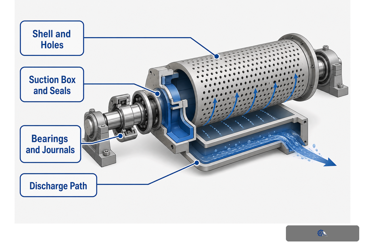
Typical suction-roll construction combines a rotating perforated shell with a stationary internal suction box or vacuum chamber. Sealing elements define the active zone and reduce leakage between the stationary and rotating components. Bearings, journals, drives, deckle arrangements and the air/water discharge path complete the working system. Machine design, rather than a generic roll label, determines the geometry and material set.
Each part requires evidence, including position-specific bearing temperature and vibration trends. Inspection should verify that shell holes remain open, uniformly clear and clean. Compare any restriction pattern with the mark observed on the sheet or machine clothing. Do seal wear, loading, or lubrication records support leakage or drag? Is the suction region as shown on the current drawing? Are bearing temperatures and vibration behaviors defined by their positions? Is the separator, piping, and the source of the vacuum able to remove the expected mixture?
| Part or path | Evidence to retain | Competing explanation |
|---|---|---|
| Shell and holes | Mapped restriction, damage and cleaning record | Clothing or furnish limits flow first |
| Suction box and seals | Zone, wear, loading, leakage and lubrication evidence | Upstream piping or pump condition |
| Bearings and journals | Trend, spectrum/route, temperature and inspection findings | Alignment, drive or external vibration source |
| Discharge path | Separator, valve, piping and water-removal condition | Gauge location masks downstream restriction |
External looks can’t confirm internal equivalence. Two rolls with similar shells may have different suction-box geometry, zones, seals, supports, allowable speeds, or service history. Never use a generic drawing to dictate limits or dimensions of an installed roll.
Evidence note: US6986831B2 describes one suction-roll arrangement with a perforated shell, internal suction box and sealing elements. The patent supports the anatomy model only. It is one design record, not proof that every roll uses the same internal geometry or that the claimed design performs better.
Which Measurements Create a Reliable Roll Baseline?
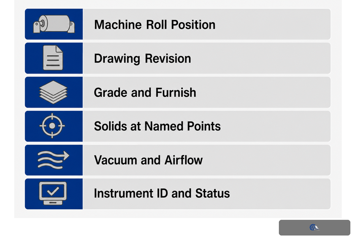
Reliable baselines are traceable records of known working conditions. Future comparison is only enabled when the record determines which grade ran, the positions where samples were taken, the instrument used, and whether felt, vacuum, load or speed changed between sampling instances. Paper mills shouldn’t compare high-speed packaging or kraft-paper production with a slower waste-paper grade unless the differences are labeled.
Start with identity: machine roll position, installed roll record, drawing revision, grade, furnish and supporting clothing. Add operating state: basis weight, speed, solids at named points, vacuum and airflow at named points, nip/load context, felt or fabric age and condition, vibration route, alignment evidence, breaks and recent changes. Finally, attach measurement assurance: instrument ID, status, method, sampling point, timestamp and owner.
| Baseline group | Minimum record | Invalid comparison warning |
|---|---|---|
| Product and furnish | Grade, basis weight, fiber/filler and chemistry state | Unlike product or unrecorded recipe change |
| Machine state | Speed, vacuum/airflow, nip/load context and recent event | Setpoint recorded but actual condition missing |
| Clothing and roll | Campaign, condition, alignment, seal/hole/bearing evidence | Aged or changed felt/fabric not labeled |
| Measurement system | Instrument, status, point, method, time and operator | Different method or shifted sample location |
| Outcome | Dryness/profile, sheet stability, quality, breaks and production effect | One input signal with no process result |
ISO 17359 helps structure a general condition-monitoring program, including operating conditions, measurement locations, acquisition and reference data. It applies broadly to machines. It does not set a threshold for an alarm for paper-machines, nor does it define which solids, vacuum, vibration or acceptance value is correct for this roll. The TAPPI guidelines and the documentation for the machine provide the context for the paper industry and the equipment, respectively.
Localized bearing signatures can be actionable inspection findings. Research on rotating equipment shows that, under certain controlled conditions, features extracted from vibration signals can classify the state of bearings. This doesn’t eliminate the baseline; it changes the next question. A confirmed bearing defect still needs process corroboration before it can explain dryness loss or justify replacing an entire roll.
Evidence note: ISO 17359:2018 was confirmed current in 2023 and governs condition-monitoring program setup, not paper-machine limits. TAPPI TIP 0502-14 (2026) lists 16 wet-end monitoring parameters, adding the industry-specific measurement context needed for this baseline.
Use the 7-Signal Roll Differential-Diagnosis Matrix
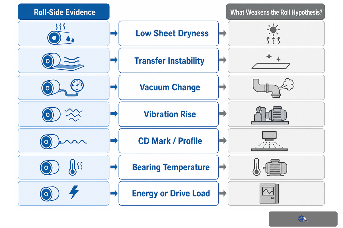
Low dryness, unstable transfer and rising vibration are symptoms with several possible causes. Other contributors include the roll, furnish, clothing, vacuum delivery, nip conditions, alignment, cover condition, bearings, drive behavior and the measurement system. Diagnose by convergence: several independent observations should support the roll hypothesis while planned checks weaken competing explanations.
- Name the symptom — Record onset time, grade, speed, machine direction or cross-machine location and the production effect.
- Collect same-window evidence — Pair sheet results with vacuum/airflow, clothing, load context, vibration and recent events.
- List competing causes — Include furnish, instruments, leaks, restrictions, seals, holes, felt, alignment, cover, bearing and drive.
- Run an approved screening check — Define in advance what safe change or inspection would strengthen or weaken the hypothesis.
- Verify before closing — Require the result to persist in a comparable window without an unacceptable secondary effect.
| Evidence type | Named observation | Boundary to retain |
|---|---|---|
| Process | Grade, furnish, speed and recent change | Same-window actuals |
| Sheet | Solids, profile, transfer and quality | Named sample point |
| Vacuum | Pressure, airflow and water discharge | Gauge and system location |
| Clothing | Felt/fabric identity, age and condition | Current campaign |
| Nip | Load context, partner roll and transfer | Machine-specific limits |
| Mechanical | Vibration, bearing, alignment and drive | Position and speed |
| Surface | Cover, shell, holes and seals | Mapped physical location |
| Instrument | Identity, status, method and timestamp | Measurement validity |
| Decision | Owner, hypothesis and acceptance rule | Approved authority |
| Signal | Roll-side evidence | What weakens the roll hypothesis? |
|---|---|---|
| Low sheet dryness | Mapped restriction/leak, changed airflow, matching solids loss | Furnish, felt or sampling change explains the same window |
| Transfer instability | Position-specific vacuum/contact or surface evidence | Draw, sheet strength or upstream moisture changed first |
| Vacuum change | Seal, hole, box, separator or pump evidence aligns | Gauge/instrument shift or process resistance changed |
| Vibration rise | Repeatable position/speed signature and bearing evidence | Drive, alignment, external source or sensor issue fits better |
| CD mark/profile | Physical pattern matches fixed roll/shell/zone position | Headbox, clothing or upstream pulsation matches timing |
| Bearing temperature | Trend, lubrication and vibration agree at one position | Ambient/load/sensor change explains the reading |
| Energy or drive load | Drag/seal/bearing condition aligns with the rise | Speed, sheet load, pump or process demand changed |
Don’t guess at classification, seriousness, and time remaining. Those are separate diagnostic stages. Vibration alarms may justify a planned check before the failure mode is diagnosed. Confirming the bearing failure mode alone does not establish that the shell or cover must be replaced. A sheet result may recover while bearing failure or mechanical risk remains. Decisions must be made at the object and evidence level that they can support.
One controlled change is a screening tool, not definitive proof of causation. Because vacuum, felt condition and furnish interact, one adjustment can improve the present operating window while hiding the larger relationship. Record the response, watch secondary effects and let the process team decide whether a designed multi-factor investigation is required.
Evidence note: A peer-reviewed rotating-machinery tutorial separates four stages: detection, fault classification, severity estimation and remaining-life estimation. Paper-industry monitoring guidance adds roll and vacuum-system context. The four-stage distinction is the guardrail; no universal vibration limit is imported.
How Should a Roll Be Inspected and Maintained Safely?
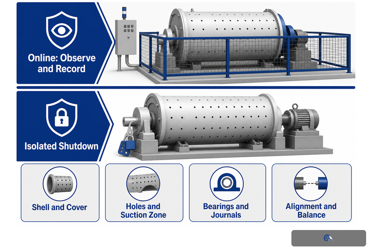
Hands-on activities such as wiping, measuring, clearing, adjusting, opening, and any work around moving rolls or nips must be done during an authorized shutdown. All these activities must be done with the hazardous energy isolated. The applicable law, machine instructions and site procedure will decide the isolation and verification steps.
The OSHA machine-guarding rule expressly covers ingoing nip points and rotating parts and states, “One or more methods of machine guarding shall be provided…”
The hazardous-energy rule is applicable when servicing machinery poses a risk of workers being exposed to unexpected energization, start-up, or the release of stored energy. The pulp and paper rule offers industry specifics with reference to paper-machine controls and guarding. These sources set safety boundaries, but a plant procedure still governs the work.
Online: observe and record
- Read fixed instruments from approved locations.
- Record sheet behavior, sound and visible condition outside guards.
- Capture trends from installed monitoring systems.
- Stop and escalate if safe access or equipment state is uncertain.
Isolated shutdown: inspect under the task plan
- Verify energy control under the site procedure.
- Inspect shell/cover, holes, seals, bearings and water path.
- Use approved measurement and NDE methods.
- Document acceptance, owner and return-to-service decision.
Shutdown Roll Evidence Pack
| Evidence item | Record | Decision use |
|---|---|---|
| Task and isolation | Approved plan, energy state, task owner | Shows the evidence was collected under the authorized boundary |
| Shell and cover | Mapped wear, damage, surface and NDE findings | Supports repair/recovering engineering review |
| Holes and suction zone | Restriction map, zone, box and seal condition | Tests the vacuum-path hypothesis |
| Bearings and journals | Trend, condition, fit and analysis findings | Keeps bearing diagnosis separate from whole-roll disposition |
| Alignment and balance | Method, reference, as-found and as-left record | Connects mechanical correction to verification |
| Acceptance package | Drawing revision, limits source, reviewer, return condition | Prevents undocumented return to service |
Maintenance timing should be based on conditions, but conditions shouldn’t be used exclusively for timing. Legal inspections, OEM requirements and site maintenance programs can create tasks to be accomplished regardless of what a condition may show. Unsourced calendar intervals, on the other hand, can’t prove a roll is healthy until the scheduled time. Write the source of the requirement next to the condition evidence.
Evidence note: Three official U.S. rules define different layers: 1910.212 for guarding, 1910.147 for hazardous-energy control during servicing, and 1910.261 for pulp and paper context. Confirm the rules applicable to your jurisdiction and site.
When Should a Roll Be Repaired, Recovered or Replaced?
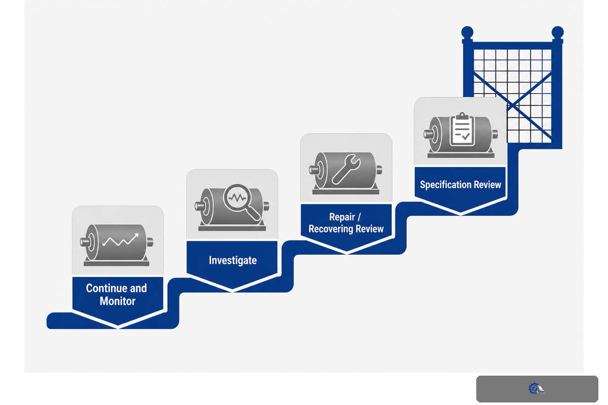
Disposition decisions must be based on converging condition, performance and verification evidence. Start by isolating the affected object: bearing, journal, shell, cover, suction box, seal system or complete roll. Next decide which action the evidence supports: continue monitoring, inspect during a planned outage, review repair or recovering, or request a machine-specific specification review.
ISO 15243 helps classify visible damage and failure modes of rolling bearings. It does not determine whether a complete paper-machine roll, a cover, a shell or a suction box must be repaired or replaced. Likewise, a health index validated on another machine cannot be imported as a universal action threshold. Base the decision on installed-roll documentation, qualified inspection, operational consequences and an authorized engineering review.
| Decision gate | Evidence needed | What blocks closure? |
|---|---|---|
| Continue and monitor | Stable output, controlled risk, no progressive evidence | Unresolved safety or deterioration signal |
| Investigate | Repeatable symptom plus a testable cause and task owner | Measurement or comparison boundary is invalid |
| Repair / recovering review | Qualified findings at the affected component and expected result | One symptom with competing causes untested |
| Specification review | Current drawing, position, duty, history, evidence pack and acceptance plan | Performance recovered under equivalent conditions without roll work |
A suction-roll case from Valmet illustrates the method: investigate the loss mechanism, define the hardware change, then verify the result. The mill outcome may not supply a service life assurance for another installation. The plan for your acceptance should define the matched operating range, primary response, secondary risks and signatories.
When evidence reaches the specification-review gate, review Press, vacuum & couch rolls for your machine position. Provide the latest drawing, roll position, machine speed, grade range, supporting clothing, as found evidence, evidence of known failure mode and the method of intended acceptance. Roll service, spare parts and other paper machinery part concerns come into play at this point.
Do you have a shutdown evidence pack or a planned roll review?
Share the installed position, drawing, grade and speed range, vacuum/airflow and solids boundary, clothing condition, trend data, inspection findings and target result. The review can then begin with traceable evidence rather than a generic roll label.
Evidence note: ISO 15243:2017 was confirmed current in 2022 and applies to rolling-bearing damage and failure modes. Its scope is narrower than whole-roll disposition. That boundary is why the table separates bearing findings, component repair review and full specification review.
Frequently Asked Questions
What does a couch roll do on a paper machine?
A couch roll supports final forming-section dewatering and helps the wet paper web leave the forming fabric for the next transfer. On many machines it’s a suction roll, but the installed arrangement determines the exact role. Diagnose it from position, vacuum and airflow, web transfer, sheet solids and fabric-contact evidence rather than from the word “couch” alone. The current drawing and sample locations settle the boundary.
What is the difference between a vacuum roll and a suction roll?
In papermaking, both labels commonly refer to a perforated or drilled rotating shell operating over a stationary internal suction zone. “Vacuum roll” is often the broader functional term. “Suction couch roll,” “suction pickup roll” and “suction press roll” add a position or duty. The current drawing, internal zones, supporting clothing and process handoff settle the meaning for one machine, because similar external shells can hide different internal arrangements. In a work order, add the machine position and asset number instead of assuming that either generic term identifies the same spare.
How is a press roll different from a couch roll?
A couch roll normally acts at the end of the forming section, where vacuum and fabric contact support final drainage and transfer. A press roll works in a press nip, where mechanical compression drives water from the sheet toward a felt and sometimes into a suction zone. The categories overlap when a suction press roll combines vacuum and nip action. Identify the installed position, force and water path before comparing performance. For a couch complaint, retain couch solids, forming-fabric contact, transfer behavior, vacuum and airflow. For a press complaint, retain inlet and outlet solids, felt condition, nip context, transfer and profile. If the roll is suction-assisted, add shell-hole, seal, suction-zone and discharge evidence. Those records reveal the true process boundary far better than the name alone.
Does higher vacuum always increase sheet dryness?
No. Indicated vacuum is only one signal. Useful dewatering also depends on airflow, sealing, open holes, furnish, speed, contact time, fabric or felt receptivity, water discharge, rewetting and the measurement method. Compare matched windows and inspect the whole air/water path before assigning a dryness change to vacuum level.
How often should a suction roll be overhauled?
There’s no safe universal interval. Follow applicable legal and site requirements, OEM instructions and the approved maintenance plan. Add service history, vibration and bearing trends, seal leakage, vacuum/airflow response, shell and hole condition, cover condition and outage opportunities. Escalate when evidence or a governing requirement supports action, not because an unsourced calendar rule says so.
Turn the Evidence Into the Next Decision
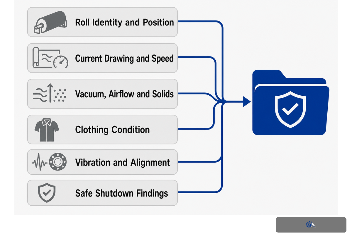
Please supply the responsible team with a single compact package containing roll identity, position and grading, current drawing and speed, symptoms of failure, baseline evidence, method of measurement, vacuum/airflow and solids boundaries, state of clothing, and history of vibration and alignment, findings of safe shutdown, competing causes rules and controlled actions and post-work acceptance. “The couch roll is weak” isn’t a useful substitute for this package.
Zejiang Paper Machinery states that it manufactures paper-machine equipment and replacement parts in Qinyang, with in-house roll and shaft machining, dynamic balancing and inspection capability. This company source supports Zejiang’s organization and service scope, not a universal engineering result.
References & Sources
The guide was checked against academic papermaking research, official safety rules, standards pages, a patent record and named manufacturer or practitioner guidance. Exact performance limits are machine specific. Competitor pages were used only to identify content gaps; their unbounded operating claims weren’t allowed.
- BioResources, rate-limiting mechanisms of water removal
- NC State, papermaking equipment and unit operations
- OSHA 29 CFR 1910.147, hazardous energy control
- OSHA 29 CFR 1910.212, machine guarding
- OSHA 29 CFR 1910.261, pulp, paper and paperboard mills
- ISO 17359:2018, condition monitoring general guidelines
- ISO 15243:2017, rolling-bearing damage and failures
- TAPPI TIP 0502-14, forming-section performance monitoring
- US6986831B2, suction-roll architecture
- Paper360, paper-machine condition monitoring
- Valmet, suction-roll performance guidance

![Refiner Plates & Screen Baskets [Complete Guide]](https://zjpapermachine.com/wp-content/uploads/2026/07/refiner-plates-screen-baskets-guide-featured-150x150.png)
![Doctor Blade: Types, Materials & How It Works [Guide]](https://zjpapermachine.com/wp-content/uploads/2026/07/doctor-blade-guide-featured-1-150x150.png)
![Pulping Equipment: How Paper Pulping Works [Guide]](https://zjpapermachine.com/wp-content/uploads/2026/07/pulping-equipment-guide-featured-150x150.png)