Get in touch with Zejiang Paper Machinery Company

Paper Machine Headbox: The Complete Guide to Types, Operation and Troubleshooting

Wet-end engineering guide
Informational support content
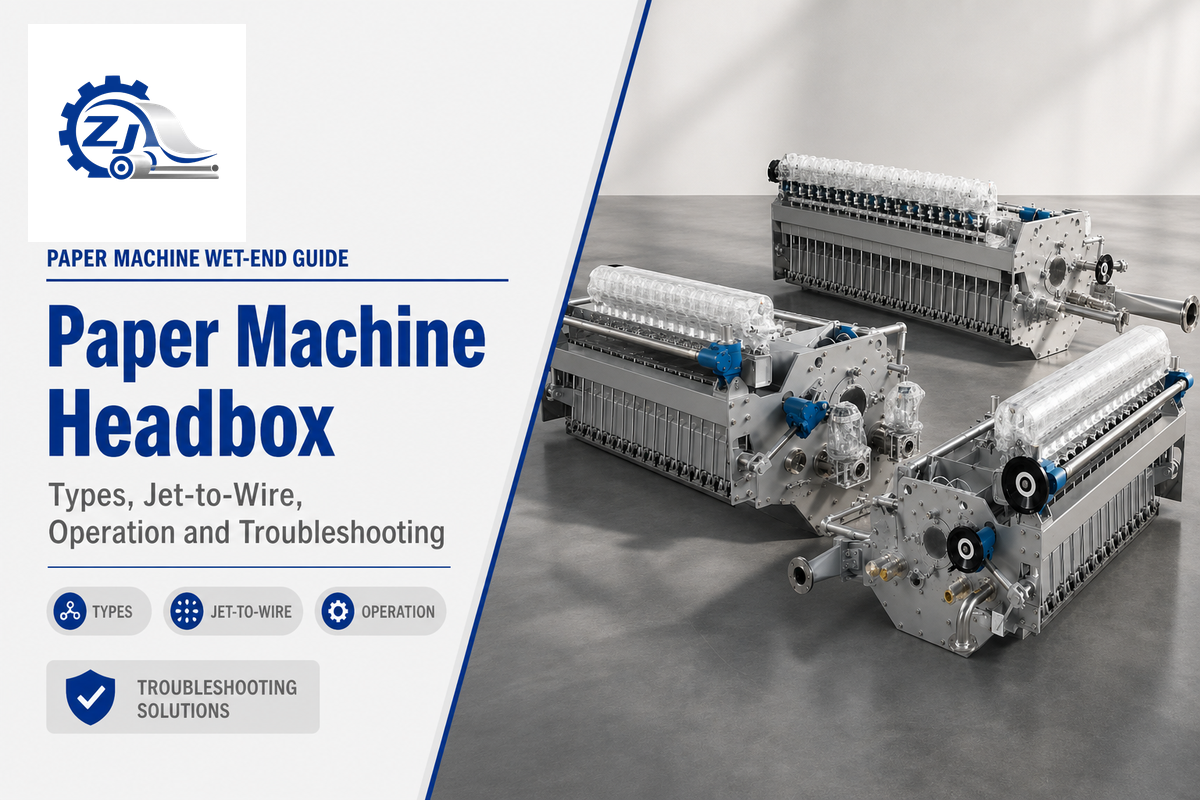
Paper Machine Headbox is the pressurized flow-distribution device between the approach-flow system and the forming wire. It converts prepared stock into a stable, cross-machine-uniform jet. The best headbox isn’t automatically the fastest or most expensive option: grade, furnish, machine speed, profile-control target, approach piping and the evidence available at commissioning must all agree.
This guide is written for mill managers, process engineers, operators and buyers who need to understand the wet-end decision before requesting a quotation. It deliberately covers education, diagnosis, maintenance and acceptance evidence. For a model, dimension, customization or RFQ discussion, see the paper machine headbox solution page. You can also review the company background on about Zejiang Paper Machinery.
Terminology note: searchers may say air cushion headbox, hydraulic headbox, paper machine headbox types, headbox paper or valmet headbox. Related questions include “types of headbox in paper machine,” “paper machine headbox design,” “paper machine headbox calculations” and “what’s a head box.” These labels point to the same educational decision, while model and price questions belong on the solution page.
1. What a paper machine headbox does in the wet end
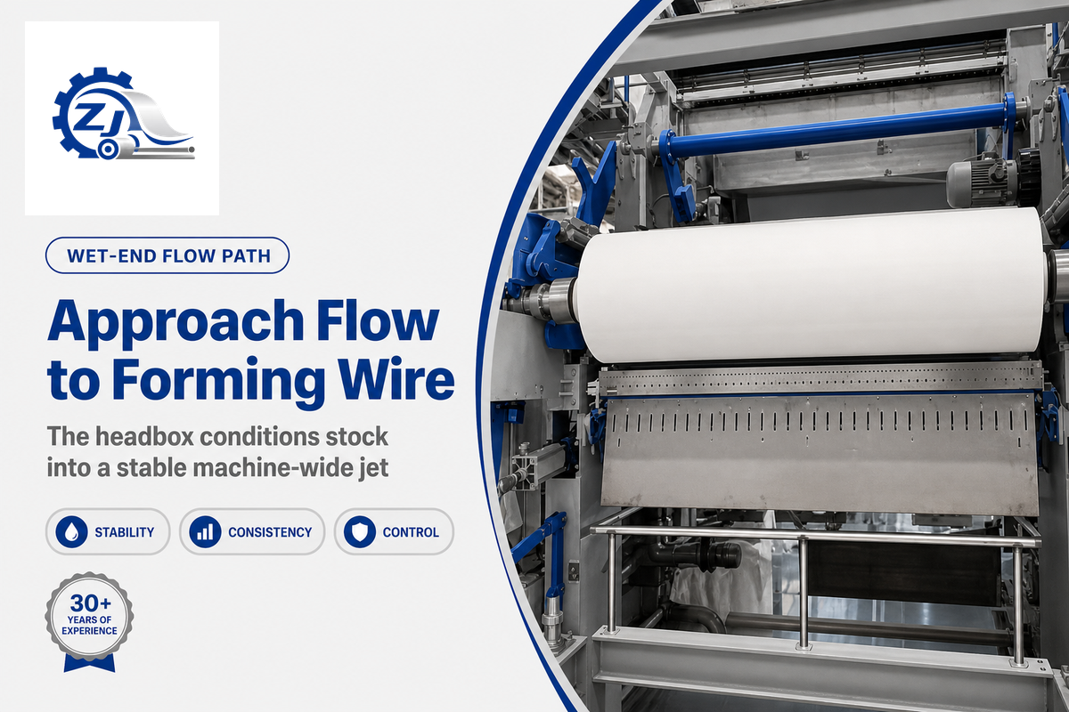
This headbox sits at the end of the approach-flow path and just before the forming section. Stock arrives after screening, cleaning, mixing and fan-pump delivery. Inside the headbox, the flow is distributed across the machine width, turbulence is conditioned, and the slice turns that flow into a thin jet. The jet then meets the forming wire, where drainage and fiber immobilisation begin. One defect that appears at the slice may therefore originate upstream in consistency, air, pressure pulsation or piping.
The practical purpose is threefold: deliver the target volume, keep the cross-machine distribution even, and present a jet whose momentum and turbulence support the intended sheet structure. Uniformity matters because a small flow difference repeated across the width can become a visible basis-weight profile, moisture profile or formation streak. This headbox is a process element, not a standalone nozzle.
| Process point | What to observe | Why it matters |
|---|---|---|
| Approach flow | Consistency, air entrainment, pressure and pulsation | Instability here can imitate a headbox fault. |
| Distribution header | Cross-machine flow split and pressure recovery | Uneven split becomes CD profile variation. |
| Slice and jet | Opening, lip condition, jet angle and jet-to-wire relation | Sets the initial fiber orientation and formation conditions. |
| Forming section | Drainage, vacuum, fabric and sheet release | Confirms whether a suspected headbox change actually improved the sheet. |
Academic engineering references describe the headbox as the final pressurized delivery element, while TAPPI training treats operation as part of the wider approach-flow and forming system. That’s why a credible troubleshooting record names the sampling point and the machine condition instead of writing only “headbox pressure changed.”
Different paper machine manufacturers, including Valmet and Voith, use their own distribution details, but the Fourdrinier hand-off principle remains the same: stable stock delivery must be proven at the wire. General paper technology references treat this hand-off as the boundary between stock preparation and forming, which is why a credible fault report always states which side of that boundary the evidence came from.
Approach piping is part of the sheet-uniformity problem; treat the headbox and its feed system as one evidence chain.
Some mill records still describe this step in terms of pulp rather than prepared stock, and the distinction matters for paper quality control. Pulp becomes furnish stock only after refining, dilution and additive mixing bring the pulp slurry down from a stock-prep consistency near 3-4% to the roughly 0.5-1% target consistency this headbox can distribute; a slurry that is still unevenly refined will show up as a headbox complaint even when the headbox itself is correctly set. A pressurized headbox therefore doesn’t act on raw pulp directly; it distributes the diluted stock flow that pulp and paper preparation has already conditioned. Confusing these terms in a paper mill maintenance record can send a technician chasing a stock-preparation issue when the real defect sits at the slice, or the reverse.
2. The three headbox types: open, air-cushion and hydraulic
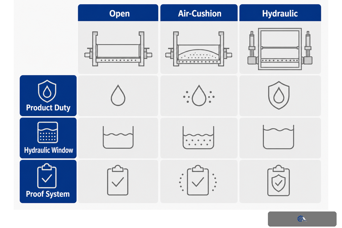
Open, air-cushion and hydraulic headboxes are different architectures, not a simple good/better/best ladder. An open unit uses the liquid level and gravity head as its main driving condition. An air-cushion unit adds a controlled air space to damp pressure changes and support a wider operating window. The hydraulic unit relies on fan-pump pressure and a designed distribution channel for higher-speed, tightly controlled delivery.
3-Layer Headbox Decision Grid
The 3-Layer Headbox Decision Grid keeps the choice practical: layer one is the product duty (grade, furnish and basis weight); layer two is the hydraulic window (speed, consistency, pressure and pulsation); layer three is the proof system (profile metric, controls and repeatable acceptance run). Each type only passes when all three layers agree.
| Type | Typical strength | Typical watch-out | Good first question |
|---|---|---|---|
| Open | Simple, accessible and suitable for lower-speed duties | Limited pressure and profile-control headroom | Is the target speed and grade stable within a gravity-fed window? |
| Air-cushion | Pressure-pulse dampening and smoother speed changes | Air-system control and sealing become part of reliability | Can the mill maintain air pressure, stock level and response together? |
| Hydraulic | High-speed delivery and integration with dilution/profile control | Approach-flow quality, pump stability and instrumentation are critical | Does the full flow loop support the requested profile and acceptance test? |
| Open + low consistency | Clear visual access during stable, lower-duty operation | Level changes directly affect driving head | Is level control repeatable through the full grade cycle? |
| Air-cushion + grade changes | More forgiving pressure response during transitions | Air pressure, seals and control tuning add checks | Are air pressure and stock level trended together? |
| Hydraulic + dilution | Zone-by-zone CD profile correction | Water quality and valve response can limit benefit | Can the loop prove command-to-response timing? |
| Any architecture | Correctly matched distribution and forming conditions | Wrong upstream assumptions create false comparisons | What is the frozen baseline for acceptance? |
| Hybrid or rebuild | Can preserve proven hardware while adding a controlled section | Interface limits can be hidden in legacy drawings | Which boundary is owned by the mill and which by the supplier? |
Client-page boundary: Zejiang’s live product page publishes typical bands of up to about 200 m/min for open, 350–1,500 m/min for air-cushion and 500–1,800 m/min for hydraulic configurations. These are attributed typical values from that page, not universal limits, guarantees or a substitute for a machine-specific calculation.
Start with furnish, basis weight, width, speed ramp, profile-control need and utility condition. Buyers who choose by type name alone can create a mismatch that no later slice adjustment can rescue. The commercial solution page owns model selection and quotation; this guide owns the decision logic that makes the request testable.
The same decision logic maps packaging and board, fine and printing, tissue, recycled, and cultural or specialty grades to different control priorities; it does not promise one architecture for every furnish. Printing paper, packaging board and tissue paper grades each set a different turbulence generator duty inside the distribution manifold, because papermaking technology treats fiber dispersion, freeness and target sheet quality as grade-specific variables rather than one fixed recipe. High-quality paper production on a hydraulic headbox therefore starts with a documented furnish, not a single “universal” turbulence setting. Headbox design decisions belong upstream of the RFQ, not as a correction afterward.
Field check: A mill operator facing a failure or delay during a hydraulic application should ask whether the root cause is upstream. Because the risk is easy to misread, Zejiang Paper Machinery engineers can record a 10% profile change, inspect a 20 mm lip and repeat a 30 min run as evidence before procurement.
For procurement teams, this distinction keeps the educational brief separate from a commercial specification. For operators, it also makes dewatering evidence visible: a headbox change should be checked alongside the forming wire, vacuum and drainage response.
3. Distribution, turbulence and the approach-flow connection
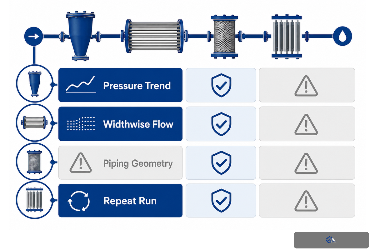
Uniform flow doesn’t mean “zero turbulence.” The headbox needs enough controlled mixing to prevent flocculation, but the distribution system must remove large-scale maldistribution and pulsation before the jet exits. Tapered headers, tubes, screens, rectifier elements and the final slice all have a hydraulic job. Their result is visible only when pressure, flow and sheet data are read together. Each manifold, tube bank and screen contributes a small pressure loss, and the header still has to deliver flow uniformly across the full machine width once those losses are added up. A manifold that is undersized for the current trim width shows up as a diagonal or one-side bias long before it shows up as a machine direction defect, because the entire paper machine width depends on that first pressure split being even.
TAPPI TIP 0404-54:2023 specifically treats approach piping as a source of machine-direction, cross-direction and diagonal basis-weight variation, and it warns that basis weight variations traced only to the slice can miss a piping-driven root cause. This is a useful contrarian check: if a CD profile repeats with the fan-pump cycle or changes when a valve upstream moves, replacing the headbox first may waste a shutdown.
| Signal | Possible mechanism | Evidence to collect before changing hardware |
|---|---|---|
| Periodic MD variation | Pump, screen or approach-pipe pulsation | Pressure trend, frequency, consistency and valve position |
| One-side CD bias | Header imbalance, air pocket or blocked passage | Widthwise pressure/flow check and clean-out history |
| Diagonal profile | Cross-flow, piping geometry or forming-section interaction | Direction of the diagonal, speed and fabric/vacuum state |
| Random streaks | Contamination, lip damage, debris or unstable stock | Photograph, sample, clean condition and repeat run |
| Edge-to-edge drift | Temperature, edge seal or boundary-flow effects | Edge profile, temperature and seal inspection |
| Slow profile wander | Sensor drift, dilution-water change or fouling | Calibration record and water-quality trend |
| Startup-only defect | Transient level, air release or recipe sequencing | Time-aligned startup trend and repeat cycle |
| Defect after cleaning | Misalignment, over-tightened lip or missed passage | Before/after photos and dimensional check |
The useful engineering question isn’t “is the headbox turbulent?” It’s “which scale of variation remains at the slice, and can the same variation be seen upstream?” Record the answer in the commissioning file so a future operator can distinguish a process drift from a mechanical change.
Field check: If a mill operator sees a failure or delay, treat the risk as a system problem. Because the root cause may be a header, Zejiang Paper Machinery engineers can inspect a 15 mm passage, record a 12% profile signal and repeat a 45 min test as evidence before changing the headbox.
4. Jet-to-wire ratio: connect a setting to sheet evidence
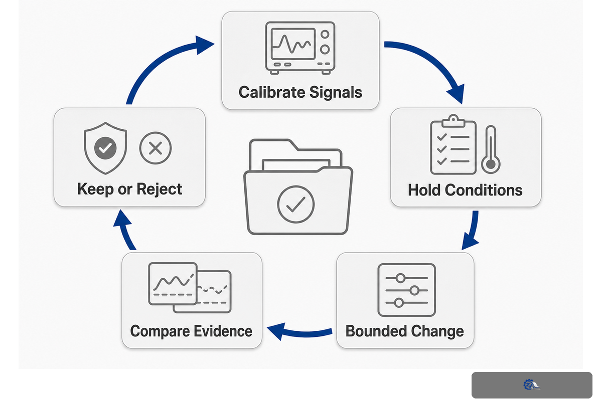
Jet-to-wire ratio compares the speed of the stock jet with the forming-wire speed. It influences fiber orientation, anisotropy, formation and drainage, but it isn’t a universal setpoint. The right value depends on furnish, consistency, slice geometry, forming fabric, vacuum and the quality target. One change that improves one grade can harm another.
Use a controlled evidence loop: freeze the grade and furnish, verify the speed measurement method, change one condition, then compare formation and orientation with the same sampling window. Don’t claim improvement from a visual “cleaner” sheet alone. Record jet speed, wire speed, consistency, basis weight, moisture, vacuum and the profile metric used by the mill.
The Jet-to-Wire Evidence Loop
- Confirm both speed signals are calibrated and time-aligned.
- Hold stock consistency, slice opening and forming conditions steady.
- Change the ratio in a small, documented step.
- Compare formation, MD/CD profile and drainage on repeated samples.
- Keep the change only if the target metric improves without a new defect.
The jet that exits the headbox lands onto the forming fabric in an angle-and-speed relationship that the mill controls through jet-to-wire ratio, not through the headbox alone. A request to increase machine speed without a matched profile-control review is a common way an otherwise sound headbox gets blamed for a downstream limitation. A stable ratio also requires stable approach flow. If pressure pulsation, air entrainment or consistency swings continue, the apparent ratio isn’t the only variable moving. TAPPI operation material and manufacturer guidance therefore place jet delivery in the context of the complete wet end.
Field check: In practice, a mill operator can see a failure when a hydraulic application changes speed. Because the risk is a hidden mismatch, Zejiang Paper Machinery engineers can record a 5% formation shift, inspect a 3 mm reference and repeat a 20 min comparison as evidence before accepting the ratio.
5. Slice opening, CD profile and dilution control
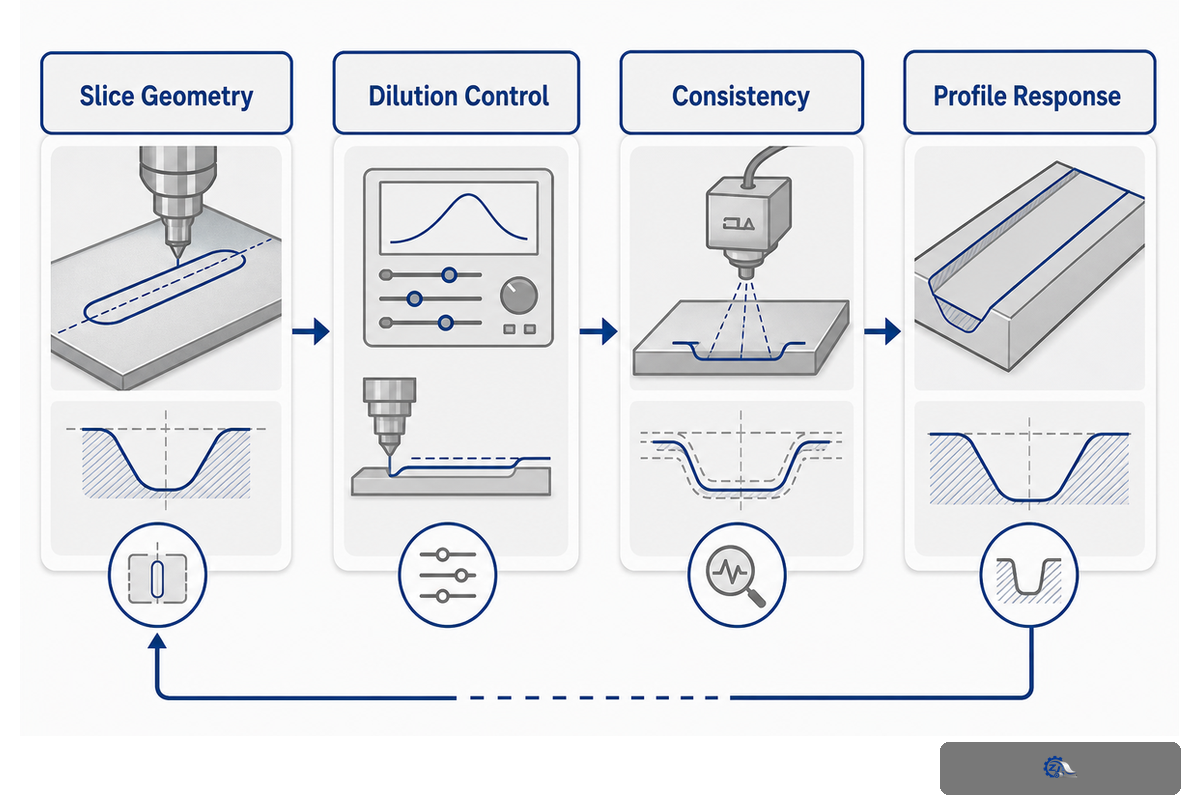
Slice opening controls the exit geometry and, together with flow and pressure, affects jet volume and shape. On a hydraulic headbox, dilution water can be used to influence cross-direction basis-weight profile. Zejiang’s product page describes automatic dilution control for CD profiling; this should be read as a documented product capability, not as a requirement that every machine use the same loop.
When a profile changes, first separate mechanical geometry from stock and control causes. One lip that’s clean but thermally distorted behaves differently from a clean lip with stable temperature. A slowly responding dilution valve produces a different signature from a blocked tube. The profile map, actuator command and measured response should be stored together. A stable CD basis weight profile is the practical proof that the slice, dilution zones and manifold are agreeing widthwise. On a comparable illustrative run, tightening the profile from a roughly 2.5 gsm width-average shift to under 1 gsm is the kind of evidence worth recording. Chasing a single reading without that context can hide a slice-geometry problem behind a dilution-loop workaround.
| Check | Question | Acceptance evidence |
|---|---|---|
| Slice geometry | Is the opening uniform and repeatable at the target load? | Feeler/laser record, lip inspection and repeat setting |
| Dilution loop | Does each zone respond in the expected direction and time? | Command-versus-response trend and alarm history |
| Consistency | Is stock consistency stable at the measurement point? | Calibrated transmitter or lab cross-check |
| Profile result | Did CD grammage improve without a new diagonal or MD issue? | Same grade, speed, sample plan and calculation method |
Field check: A production operator who sees a profile failure shouldn’t assume the dilution valve is the root cause. Because a control delay can create risk, Zejiang Paper Machinery engineers can inspect a 4 mm lip edge, log a 2% response shift and repeat a 30 min run as evidence.
6. Troubleshooting streaks, pulsation and poor formation
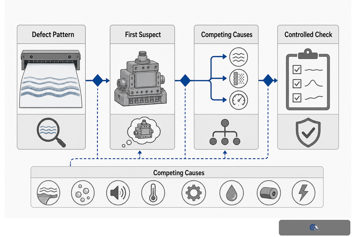
A credible headbox diagnosis requires three things to converge: the defect pattern, a process signal and a controlled check. “The headbox is the first suspect” is a useful starting hypothesis, not a conclusion. Approach-flow, stock preparation, wire condition, vacuum and drainage can produce similar symptoms.
Use the following isolation order. First photograph and map the defect in machine and cross-machine coordinates. Next compare pressure, consistency and flow trends with the defect frequency. Then inspect the slice, distribution elements and cleanliness under an approved isolation procedure. Finally run one controlled change and repeat the sample. If the defect follows an upstream valve or pump cycle, downgrade the headbox-only hypothesis.
| Symptom | First alternatives to rule out | Safe next evidence |
|---|---|---|
| Regular MD bars | Fan pump, screen, approach-pipe pulsation | Frequency analysis against pressure and flow trend |
| Fixed CD streak | Blocked passage, lip nick, dilution valve | Widthwise inspection and actuator response map |
| Flocculation or cloudy formation | Consistency, retention chemistry, mixing energy | Stock sample and formation image at matched speed |
| Defect only during grade change | Transient recipe, air release, speed ramp | Time-stamped changeover log and repeat transition |
This system-level method is why the existing solution page shouldn’t be duplicated as a second sales page. The blog answers “what should I check and prove?” while the solution page answers “which configured headbox can we supply?”
Field check: When a mill operator reports a streak failure or delay, the risk is a wrong replacement. Because the root cause may be the approach flow, Zejiang Paper Machinery engineers can inspect a 6 mm edge, record a 3% frequency shift and repeat a 60 min run as evidence before procurement.
7. Cleaning, inspection and maintenance without creating a new defect
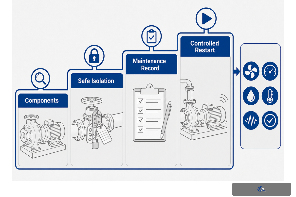
Cleaning is more than removing visible stock. Operators should verify the slice lips, seals, screens, tubes, rectifier elements, drains, sensors and calibration references that influence the next run. One clean component with a damaged edge can create a worse streak than a visibly dirty component. Maintenance records should identify the exact location, condition, action and person responsible.
Any internal inspection, pressure release, chemical cleaning or access to moving equipment must follow the mill’s approved isolation and lockout procedure. The correct sequence is site-specific; this guide doesn’t replace the safety procedure or risk assessment. Keep the pre-clean and post-clean photographs, pressure/temperature state and restart checklist with the work order.
Maintenance baseline
- Confirm the headbox is isolated, drained and at a verified safe state.
- Inspect lips and seals for nicks, wear, deposits or distortion.
- Check passages, screens and rectifier elements for plugging or damage.
- Verify sensor zero, calibration date and signal plausibility.
- Run a controlled restart and compare the profile with the last accepted baseline.
TAPPI condition-monitoring discussions support repeatable checks, but intervals depend on furnish, chemistry, contamination load and operating hours. Calendar-only intervals can miss rapid fouling; a condition-only program can miss a slow calibration drift. Use both the schedule and the evidence.
Component vocabulary for a walkdown: label the step diffuser, tube banks and nozzles, screen plate, edge deckle, white water, formation index, lockout tagout, design envelope, headbox lip, consistency control, flow stability and the procedure to adjust the slice gap in the inspection sheet. Using the same names in the drawing, PLC list and maintenance record prevents a useful observation from becoming an ambiguous note.
8. Retrofit feasibility: the Headbox Retrofit Data Card
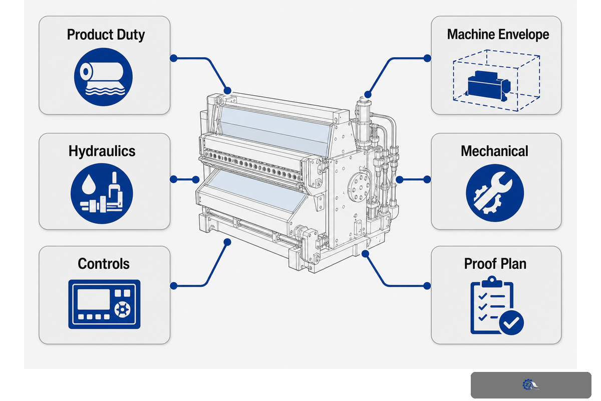
Before asking for a retrofit price, freeze the operating envelope. Suppliers need more than width and speed. The approach system, fan pump, dilution-water quality, control platform, available space, elevation, utilities, forming-wire geometry and acceptance method determine whether a proposed headbox can be integrated without moving the problem downstream.
The Headbox Retrofit Data Card
| Product duty | Grade family, furnish, basis-weight range, moisture target and chemicals |
| Machine envelope | Trim width, design speed, normal speed, speed ramp and current jet/wire data |
| Hydraulics | Fan-pump curve, approach-pipe layout, consistency, pressure, air-removal and pulsation history |
| Controls | PLC/DCS platform, I/O list, dilution zones, alarms, interlocks and historian tags |
| Mechanical | Elevation, nozzle orientation, access, drains, lifting path and forming-section clearance |
| Proof plan | Formation metric, CD/MD profile method, sample plan, repeat runs and sign-off owner |
OEM rebuild references show why integration belongs in the first conversation. If a new hydraulic headbox needs cleaner dilution water, a different fan-pump operating point or new control interlocks, those are part of the project boundary. They shouldn’t appear later as “unexpected extras.” A retrofit headbox destined for a new paper machine order faces the same integration questions as a rebuild: air cushion pressure stability within an illustrative 5 kPa band, dilution-water quality and control interlocks. Grade examples worth stress-testing during acceptance include linerboard, tissue and coated printing grades, since each stresses the slice lip opening and profile-control loop differently. For company context before a supplier discussion, see Zejiang Paper Machinery company background.
Field check: A mill operator planning a retrofit can face a failure, delay or budget risk when drawings are incomplete. Because the root cause is often an interface, Zejiang Paper Machinery engineers can inspect a 25 mm clearance, record a 10% utility margin and repeat a 30 min interface test as evidence before procurement.
9. RFQ and commissioning: buy measurable outcomes

A good RFQ asks for a decision-ready configuration and a verifiable acceptance path. State the grade, furnish, target range, normal speed, width, utilities, control interfaces and known defect. Ask the supplier to identify assumptions, excluded work and the data needed to confirm the design. The headbox solution page is the right place to move from this educational checklist to a configured quotation.
| RFQ item | Weak wording | Decision-ready wording |
|---|---|---|
| Speed | “High speed” | Normal and maximum speed, ramp time and attributed design basis |
| Profile | “Improve uniformity” | Metric, sampling width, calculation, baseline and target tolerance |
| Controls | “Automatic control” | Zones, response time, PLC protocol, alarms and interlock ownership |
| Acceptance | “Pass FAT/SAT” | Frozen grade, furnish, speed, sample plan, repeat runs and sign-off roles |
At commissioning, compare like with like. Document the grade, furnish, consistency, speed, jet-to-wire ratio, wire condition, vacuum, sampling point and comparison window. The result is credible when a second run can reproduce it. One attractive sheet sample is a lead, not proof.
Illustrative test checkpoints (not universal setpoints): a mill may log 30 m/min, 60 m/min and 90 m/min during a controlled ramp; 0.5%, 1.0% and 1.5% consistency checks; 20 kPa and 40 kPa pressure points; 10 Hz pulsation bands; 2 mm lip observations; 60 °C cleaning-temperature records; and 15 min, 30 min and 60 min repeat windows. The point is a traceable measurement sequence, not a magic number.
For a longer baseline, the same record can include 1 min signal check, 5 min stabilization, 10 min sampling, 20 min trend review, 25 min purge, 45 min repeat, 120 min endurance, 3 mm seal gap, 4 mm edge check, 5 kPa alarm margin, 2 Hz noise band, 8 rpm pump variation and 12 months of calibration history. These values illustrate how to label a test, not what every machine must use.
Have a headbox symptom or retrofit data set?
Send the operating envelope and the defect evidence through the Request a headbox data review form. The engineering discussion can then stay focused on the right type, interfaces and acceptance measurements.
Send the operating envelope and the defect evidence through the Request a headbox data review form. The engineering discussion can then stay focused on the right type, interfaces and acceptance measurements.
10. Monitoring outlook: what to watch next
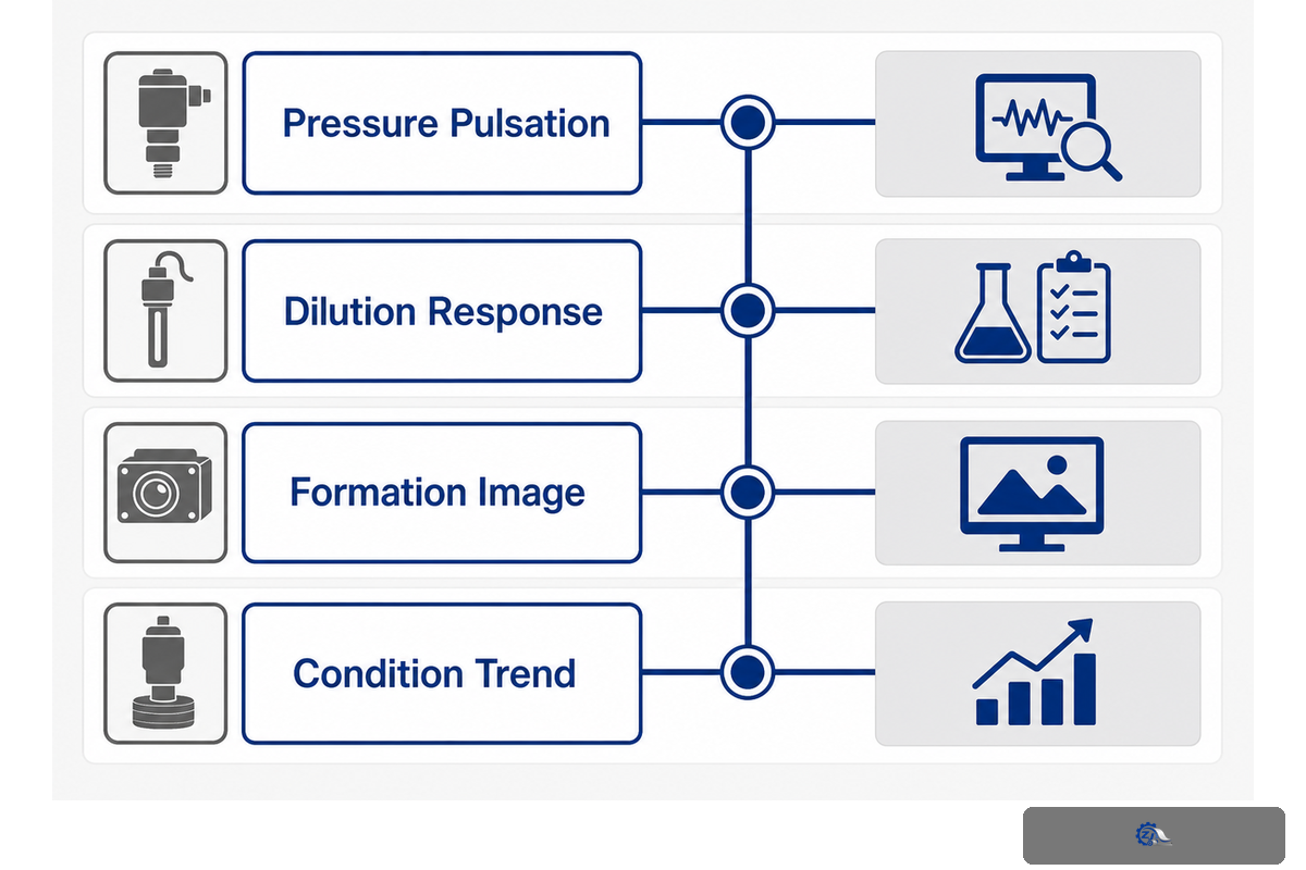
Paper-machine monitoring is moving toward earlier detection of drift: pressure and flow signatures, sensor plausibility, actuator response, formation images and condition-based maintenance. Recent TAPPI trade coverage and patent publications are useful direction signals, but a patent isn’t field-performance proof and a trend article isn’t a guaranteed return-on-investment case.
The near-term opportunity is simple instrumentation discipline. Tag the fan-pump pressure, approach consistency, slice position, dilution command, measured response, wire speed and profile result with a common timestamp. When a defect appears, the mill can test whether the signal changed first. That evidence is more valuable than adding a sensor without a decision rule.
| Monitoring signal | Early warning question | Action boundary |
|---|---|---|
| Pressure pulsation | Is frequency or amplitude drifting from the accepted baseline? | Inspect upstream pump, screen and piping before local adjustment. |
| Dilution response | Does a command produce the expected CD response and timing? | Check valve, water quality, calibration and PLC scaling. |
| Formation image | Does texture change while process values remain apparently stable? | Check camera, sampling and hidden furnish/chemistry changes. |
| Condition trend | Is a slow drift visible across accepted runs? | Plan inspection before the drift becomes a shutdown defect. |
The winning practice isn’t “maximum automation.” It’s a traceable loop from signal to decision to verified result. That principle keeps future headbox upgrades measurable and protects the mill from replacing sound hardware to compensate for an unmeasured process change.
Field check: In practice, a mill operator can catch a failure before shutdown when a monitoring signal drifts. Because the risk is false confidence, Zejiang Paper Machinery engineers can inspect a 2 mm reference, record a 4% trend change and repeat a 15 min check as evidence.
Frequently Asked Questions
What is the purpose of a headbox?
A headbox receives prepared stock and delivers a controlled jet across the machine width. It coordinates flow, pressure, turbulence and slice conditions; diagnose it with the approach-flow and forming section, not as an isolated nozzle. This view prevents false repairs.
What are the common types of paper machine headbox?
The common architecture families are open, air-cushion and hydraulic. Open designs use a gravity/liquid-level driving condition, air-cushion designs use an air space to damp pressure changes, and hydraulic designs use pressurized flow distribution. The right choice depends on grade, furnish, speed, profile-control needs and integration constraints. The typical speed bands published by a supplier are useful context, not universal limits. Compare those ranges with the mill’s actual grade trials and control capability during the grade and speed window being evaluated.
How does a headbox affect paper formation?
A headbox affects formation through cross-machine distribution, turbulence conditioning, slice geometry and the jet-to-wire relationship. These factors influence how fibers orient and how drainage begins on the forming wire. Formation changes can also come from consistency, retention chemistry, wire condition, vacuum or approach-flow pulsation, so compare those variables before assigning the result to the headbox alone.
What data should be included in a headbox RFQ?
Include grade and furnish, basis-weight range, trim width, normal and maximum speed, consistency, fan-pump data, approach-pipe layout, dilution-water condition, controls and available space. Add the current defect pattern and the acceptance metric, sample plan and sign-off owner. This lets a supplier state assumptions and interfaces clearly instead of pricing an undefined “high-speed” replacement.
When should a mill consider a hydraulic headbox?
Consider a hydraulic architecture when the machine duty, approach-flow system and controls can support pressurized, stable delivery and the mill needs the associated speed or profile-control headroom. Don’t choose it solely because the name sounds more advanced. Verify pump stability, piping, dilution water, instrumentation, PLC interfaces and the acceptance test first. Lower-complexity designs can be the better fit when those conditions aren’t ready. Confirm the choice with a grade trial and a clear acceptance owner. Record baseline before hardware changes.
What does “a headbox provides uniform paper quality” actually mean in practice?
When a specification says a headbox provides uniform paper quality, it’s describing profile stability, not a guarantee independent of the rest of the machine. A headbox is designed and sized for a duty window, and the quality and properties of the finished paper sheet still depend on stock preparation, forming, pressing and drying all working inside that same window.
Different paper grades, including printing paper, packaging board, tissue and specialty sheet, set different targets for dispersion, closed-loop dilution response and basis weight profile. High-speed paper machines make this coordination stricter, not optional, because there is less time to correct a slow response before it shows up across the sheet.
How is headbox performance actually measured before and after a change?
Headbox performance is measured the same way before and after any change: formation, CD and MD basis weight profile, moisture profile and fiber orientation on a frozen grade and speed. A vendor may say a design ensures uniform delivery, but the quality requirements that matter are the mill’s own acceptance numbers, not a generic sheet properties claim. Track the same sheet properties across the comparison window so “the headbox ensures better paper” is a checked result, not a sales sentence.
What is the purpose of a headbox?
This headbox receives prepared stock, distributes it across the machine width and delivers a controlled jet to the forming wire. It must be read with the approach-flow and forming section because pressure, consistency and drainage all affect the sheet. Record the sample point, grade and machine condition whenever you assess the result. In practical terms, the headbox is the hand-off between a prepared suspension and a forming event. Useful records name the inlet condition, distribution state, slice condition and resulting sheet observation, so a later operator can test a local symptom without assuming that the whole headbox needs replacement.
How can a mill separate a headbox fault from an approach-flow fault?
Map the defect, compare its timing with pressure and consistency trends, inspect the slice and upstream passages, then repeat one controlled change. If the defect follows a pump or valve cycle, the headbox-only hypothesis is weakened. Repeat the check after the upstream condition is stable before ordering a replacement. Keep the result in the shift log so procurement sees evidence instead of a guess.
What makes a commissioning result credible?
Freeze grade, furnish, consistency, speed, jet-to-wire method, sampling point and profile calculation. Repeat the run and retain the data so another operator can reproduce the result. Include the calculation method and acceptance owner in the record. Keep the raw trend and the signed comparison sheet with the project file for later audits.
Does a hydraulic headbox always deliver better paper?
No. Hydraulic designs can offer speed and profile-control headroom, but benefit depends on stable approach flow, suitable controls, utilities and a matched forming section. The highest-complexity option isn’t automatically the best fit. Simpler architectures with stable evidence can outperform a larger system that the mill can’t maintain. Confirm the decision with a repeatable grade trial.
What should be in a headbox maintenance record?
Record isolation state, inspected location, lip and seal condition, passage cleanliness, sensor calibration, corrective action, operator and post-startup comparison with the accepted baseline. Add the work-order number and calibration reference so the next shift can trace the decision. Note any deviation, temporary repair and follow-up due date.
References & Sources
The technical discussion is based on the following sources, with client-page facts kept explicitly within their published scope:
- Parason: Working principle of a headbox — stock path, distribution and jet delivery.
- Valmet headbox product family — grade and machine integration context.
- ScienceDirect engineering topic: Headboxes — academic definition and approach-flow context.
- TAPPI paper machine headbox operation — operating and forming context.
- TAPPI TIP 0404-54:2023 and ANSI listing — approach-piping guidance.
- TAPPI/ANSI T 546 om-22 — machine-direction grammage variation measurement.
- Toscotec headbox rebuild reference — retrofit integration context.
- TAPPI Paper360 condition-monitoring discussion — monitoring direction.
- US20080023167A1 and CA3301242A1 — patent signals used only as technology-direction evidence.
- Zejiang Paper Machinery headbox page — attributed type bands, hydraulic dilution-control description and application context.
Last reviewed: September 2, 2026. Operating limits, standards editions and acceptance criteria must be confirmed for the specific machine and market.


![Refiner Plates & Screen Baskets [Complete Guide]](https://zjpapermachine.com/wp-content/uploads/2026/07/refiner-plates-screen-baskets-guide-featured-150x150.png)
![Doctor Blade: Types, Materials & How It Works [Guide]](https://zjpapermachine.com/wp-content/uploads/2026/07/doctor-blade-guide-featured-1-150x150.png)
![Pulping Equipment: How Paper Pulping Works [Guide]](https://zjpapermachine.com/wp-content/uploads/2026/07/pulping-equipment-guide-featured-150x150.png)